Intro
A few years ago, Elektor Magazine had an interesting DAC project with high end aspirations based on the Burr-Brown (now Texas Instruments) 1794 DAC for a modest price.
I bought one and although it sounded very good indeed, it never got used very much. Mainly because it was clumsy to use for me (and lacking a proper enclosure). It was slow (maybe it’s better with a Raspberry 4 now), the touch screen is too small for me (and being of the resistive kind instead of capacitive, not very responsive neither). I did manage to get Airplay working (with a workaround for the infamous 16 bit silence of this DAC) but it turned out not to be reliable.
I also had a Pi Zero W laying around (which I won with a Elektor contest a few summers ago) and the idea ripened to try out if I couldn’t simplify things a lot by combing the Pi Zero W with the Elektor DAC and just use it as an Airplay receiver. After all, this was the only functionality I needed. Airplay is lossless but limited to 16 bit and 48 kHz sampling rate. But that’s fine for me since I have very few recordings at higher bit depths and sampling rates.
Although you will find plenty of “How To” articles on the Internet on how to build an Airplay receiver starting from a Raspberry, many are outdated and are sometimes full of errors :-( So, here is my attempt to explain how you can build an Airplay receiver based on a Raspberry Pi Zero W and a DAC Hat (in this case the Elektor Audio DAC but it should work with many [commercial] others as well) and the kernel 4.x series of Raspberry Pi OS (this is important since these instructions will definitely not work on kernel 3.x based Raspberry Pi OS images and probably will not work when kernel 5.x will be used in Raspberry Pi OS).
Setting up the Raspberry Pi Zero W
The first thing we need is a fresh Raspberry Pi OS (32-bit) Lite Minimal image based on Debian Buster. This is the direct download link.
Use your favourite flash image tool to flash the Raspberry Pi OS Image to your SD Card. I always use BalenaEtcher.
Be aware that this installation is fully done on the command line. So no fancy GUI here which only wastes space and CPU cycles. And since the Raspberry Pi Zero W will run headless (i.e. no monitor or LCD screen attached) once everything is set up, there is really no reason to install a GUI.
To save you some time searching for it, this is the default username and password to log in the Raspberry Pi OS once it has booted:
  username: pi
  password: raspberry
The first time you start up your Raspberry with a freshly flashed SD card you will see a message that the root file system is being resized. This is normal. After a few seconds, your Raspberry will reboot after which you can log in with the above mentioned username and password.
Now we need to set up your Raspberry. To do this type:
sudo raspi-config
and hit enter.
Things you can (and have to) set up using the raspi-config program:
-
Localisation Options:
- Change Time Zone (the default is set to UK/London)
- Change Keyboard Layout (the default is set to UK English keyboard layout)
- Change WLAN Country (you can skip this since the Wireless LAN setting you need to set later on will ask for your country if it wasn’t already set)
-
Network Options:
- Hostname (optional but the hostname will be taken over as the name of the Airplay Receiver to identify this Airplay station)
- Wireless LAN
- SSID (the name of your WiFi network) and password
-
Update (Update this tool to the latest version)
- This will only work once the WiFi network is configured. So it’s a good check if you configured Wireless LAN correctly.
Reboot your Pi and type in:
ifconfig
In the resulting output you should see a line containing wlan0. If you configured
the Wi-Fi connection correct, you should see something like:
`inet addr:192.168.2.x` (or similar)
Only proceed with the next steps when you have a working network connection!
Now we do a full update of the Raspberry Pi OS with the following commands:
sudo apt-get update
followed with:
sudo apt-get upgrade # this can take quite some time to finish
and:
sudo rpi-update
Reboot your Pi again.
Since we’re using WiFi, it is recommend to turn off WiFi Power Management. According
to the install instructions
of shairport-sync (which we will install later):
WiFi Power Management will put the WiFi system in low-power mode when the WiFi system considered inactive, and in this mode it may not respond to events initiated from the network, such as AirPlay requests. Hence, WiFi Power Management should be turned off.
You can turn off WiFi Power Management with the following command:
sudo iwconfig wlan0 power off
Reboot your Pi once again.
Build and install airplay (shairport-sync):
First, we need to install all the packages needed to build shairport-sync:
sudo apt-get install build-essential git xmltoman autoconf \
    automake libtool libpopt-dev libconfig-dev libasound2-dev \
    avahi-daemon libavahi-client-dev libssl-dev libsoxr-dev
Next, we need to download the shairport-sync source code, configure, compile
and install it. This can be done with the following command sequence:
git clone https://github.com/mikebrady/shairport-sync.git
cd shairport-sync
autoreconf -fi  # This takes some time where nothing seem to happen!
./configure --sysconfdir=/etc --with-alsa --with-soxr --with-avahi --with-ssl=openssl --with-systemd
make
sudo make install
We have now build and installed shairport-sync. The next step is to configure it.
These are the most important options for the shairport-sync configuration file
stored at: /etc/shairport-sync.conf. I’m using the nano editor here with is part
of the default install of the Raspberry Pi OS:
sudo nano /etc/shairport-sync.conf
Add these lines to the /etc/shairport-sync.conf file:
alsa =
{
  output_device = "hw:0";
  mixer_control_name = "PCM";
};
For the next step we need to use the root password which is not set yet. We can do this with the following command:
sudo passwd root
Now we’re ready to enable shairport-sync to start automatically on boot up (note
that you will have to give the root password you just created, not your login
password!):
systemctl enable shairport-sync
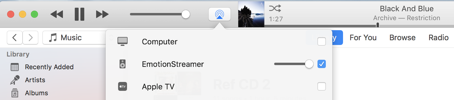
Finally, reboot the Pi. Once the Pi Zero W has finished starting up, you should see the name of your Airplay receiver (EmotionStreamer in my case) in your preferred music player.
Setting up Audio
Now that we have Airplay running on our Raspberry Pi Zero W we now need to convince our Raspberry to stream the audio, we send to it, to the Elektor DAC. Luckily we already know that the Elektor DAC is working in the same way (or is compatible with) the HiFiBerry-DAC. So we can use the same configuration as for the HiFiBerry-DAC.
From the HiFiBerry documentation web page Configuring Linux 4.x or higher we learn that we need to do the following:
Edit the config.txt file located in the /boot directory:
sudo nano /boot/config.txt
Remove the line (or put a # in front to out comment it):
dtparam=audio=on
Add this line after the line # Additional overlays and parameters ...:
dtoverlay=hifiberry-dac
Now we need to create a asound.conf file in the /etc directory:
sudo nano /etc/asound.conf
And copy these lines into it:
pcm.!default  {
type hw card 0
}
ctl.!default {
type hw card 0
}
Now reboot the Pi Zero W.
With the aplay command we can now check if the DAC is found:
aplay -l
Will show this kind of output:
card 0: sndrpihifiberry [snd_rpi_hifiberry_dac], device 0:HifiBerry DAC HiFi pcm5102a-hifi-0 [HifiBerry DAC HiFi pcm5102a-hifi-0]
    Subdevices: 0/1
    Subdevice #0: subdevice #0
If all went well, you should see HifiBerry DAC appearing in the output of
the aplay -l command and you can now stream and hear your favourite music on
the Elektor DAC!
PS. From the above it’s also clear that this way of working can also be used for
other DAC Hats as long as there is a corresponding (or compatible) dtoverlay for it.
Making a nice enclosure
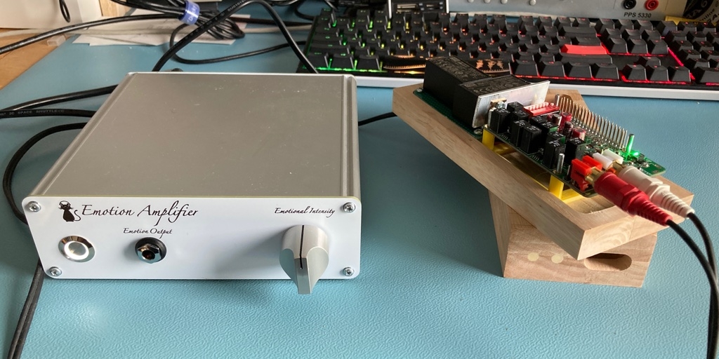
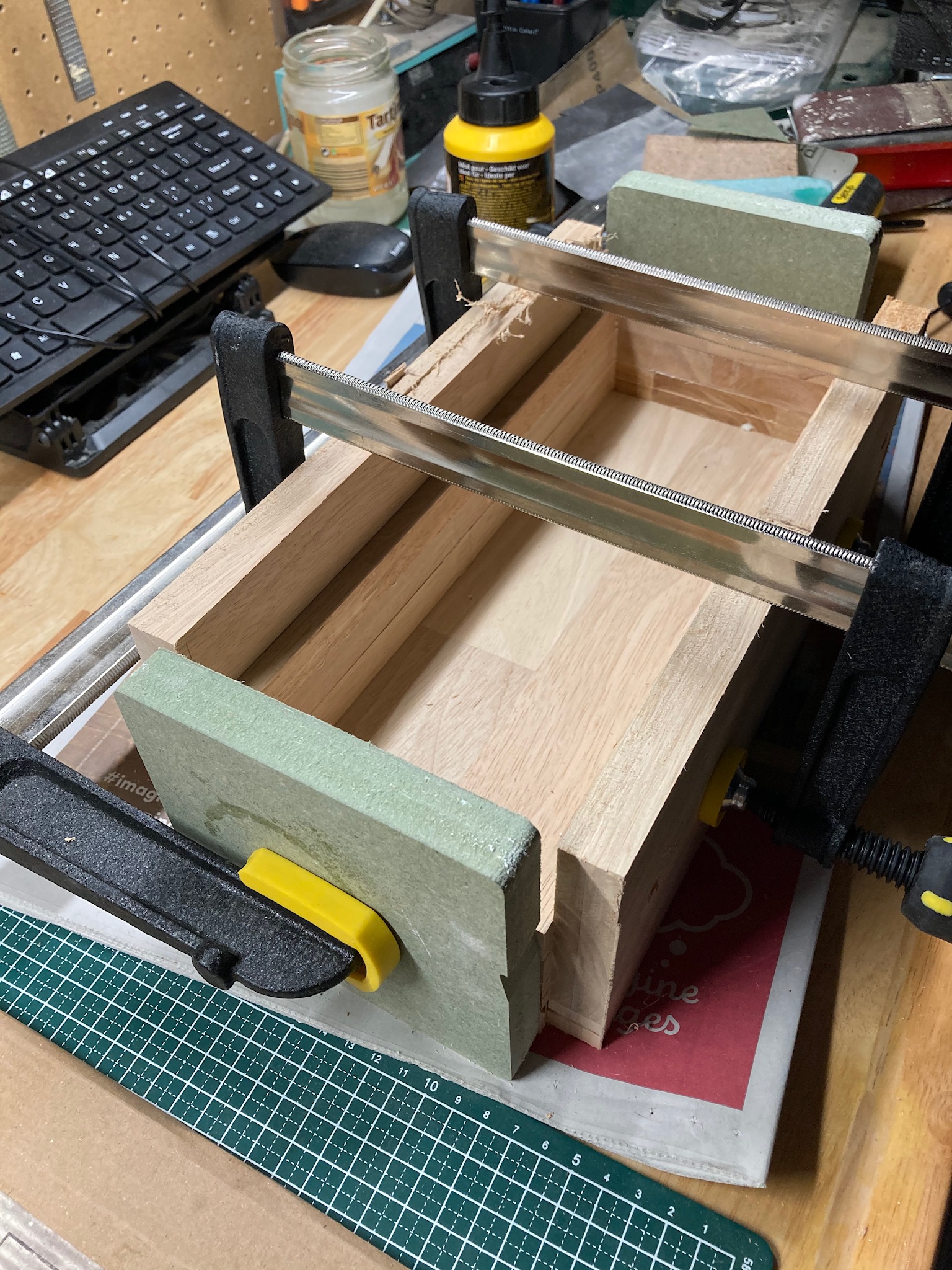
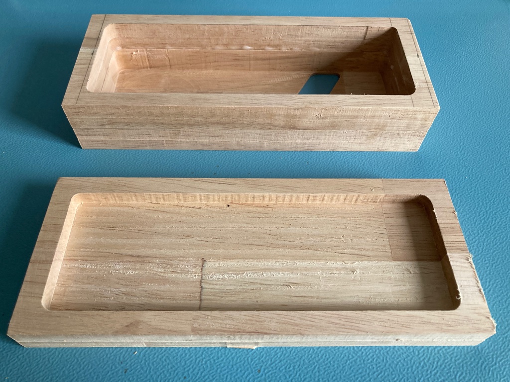
Since we use WiFi and I don’t see any really easy way to add an external WiFi antenna to a Pi Zero W (unless we would use a USB WiFi dongle) we can’t use a metal enclosure. So I went back to my heap of wood leftovers and found some nice pieces of rubberwood I could use for this project. These were 18 mm thick and I needed 3 layers to build a box that was high enough to accept all the electronics.
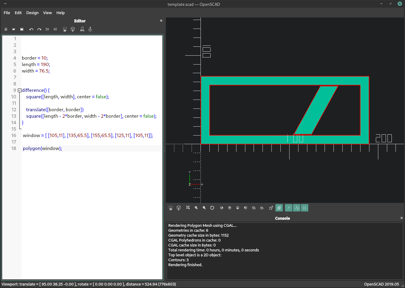
I used OpenSCAD to draw a template for the enclosure and then used Estlcam to generate the corresponding gcode for the top, mid and bottom layer. This is the OpenSCAD code I used:
border = 10;
length = 190;
width  = 76.5;

difference() {
    square([length, width], center = false);

    translate([border, border])
    square([length - 2*border, width - 2*border], center = false);
}

window = [ [105,11], [135,65.5], [155,65.5], [125,11], [105,11]];

polygon(window);
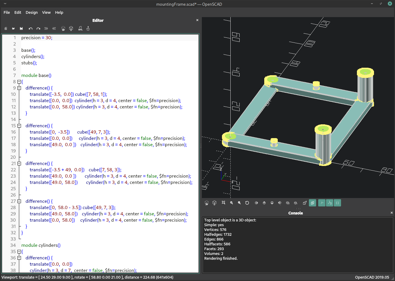
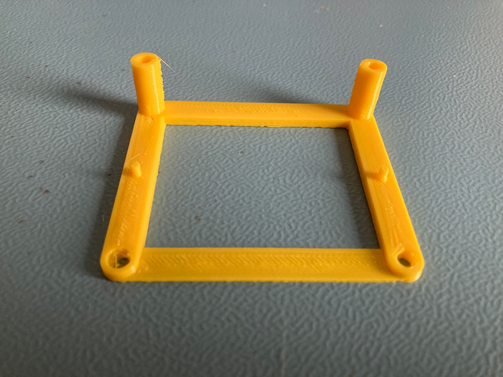
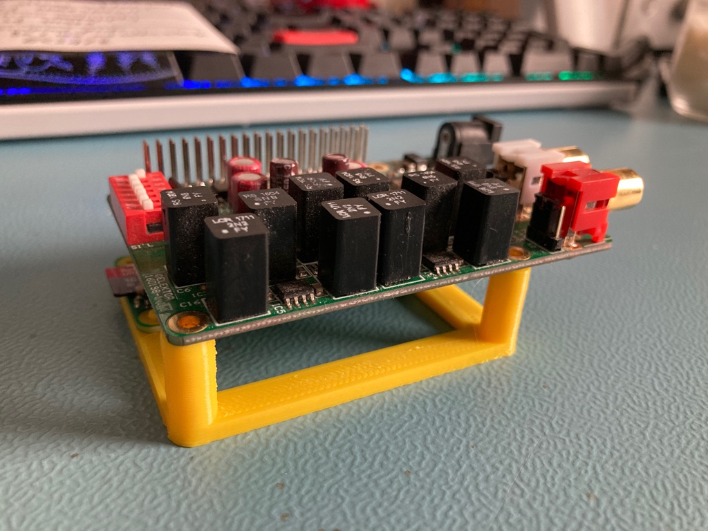
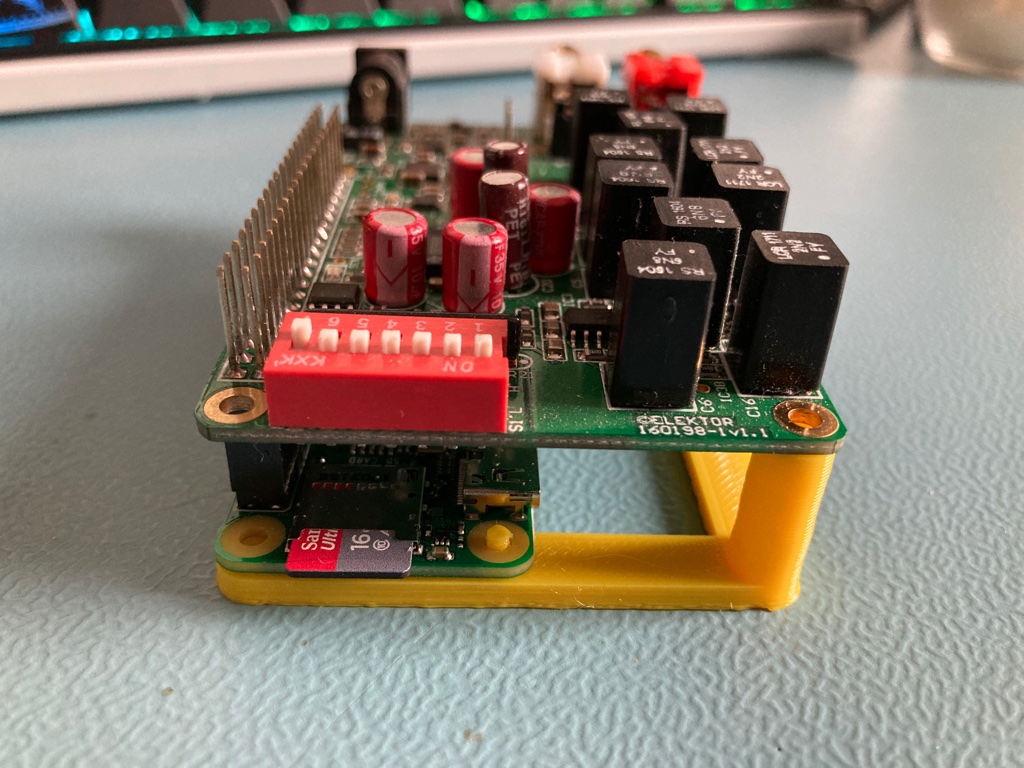
To keep the Pi Zero W and Elektor DAC nicely in place, I designed a support frame. This is the openSCAD code:
precision = 120;

base();
cylinders();
stubs();

module base()
{
    difference() {
        translate([-3.5,  0.0]) cube([7, 58, 1]);
        translate([0.0,  0.0])  cylinder(h = 3, d = 4, center = false, $fn=precision);
        translate([0.0,  58.0]) cylinder(h = 3, d = 4, center = false, $fn=precision);
    }

    difference() {
        translate([0,  -3.5])       cube([49, 7, 3]);
        translate([0.0,  0.0])      cylinder(h = 3, d = 4, center = false, $fn=precision);
        translate([49.0,  0.0 ])    cylinder(h = 3, d = 4, center = false, $fn=precision);
    }

    difference() {
        translate([-3.5 + 49,  0.0])    cube([7, 58, 3]);
        translate([49.0,  0.0 ])        cylinder(h = 3, d = 4, center = false, $fn=precision);
        translate([49.0,  58.0])        cylinder(h = 3, d = 4, center = false, $fn=precision);
    }

    difference() {
        translate([0,  58.0 - 3.5]) cube([49, 7, 3]);
        translate([49.0,  58.0])    cylinder(h = 3, d = 4, center = false, $fn=precision);
        translate([0.0,  58.0])     cylinder(h = 3, d = 4, center = false, $fn=precision);
    }
}

module cylinders()
{
    difference() {
        translate([0.0,  0.0])
        cylinder(h = 3, d = 7,  center = false, $fn=precision);
        cylinder(h = 3, d = 4, center = false, $fn=precision);
    }

    translate([0.0,  58.0])
    difference() {
        cylinder(h = 3, d = 7,  center = false, $fn=precision);
        cylinder(h = 3, d = 4, center = false, $fn=precision);
    }

    translate([49.0,  0.0 ])
    difference() {
        cylinder(h = 3+15, d = 7,  center = false, $fn=precision);
        cylinder(h = 3+15, d = 4, center = false, $fn=precision);
    }

    translate([49.0,  58.0])
    difference() {
        cylinder(h = 3+15, d = 7,  center = false, $fn=precision);
        cylinder(h = 3+15, d = 4, center = false, $fn=precision);
    }
}

module stubs()
{
    translate([23.0,  0.0])     cylinder(h = 6, d = 2, center = false, $fn=precision);
    translate([23.0,  58.0])    cylinder(h = 6, d = 2, center = false, $fn=precision);
}
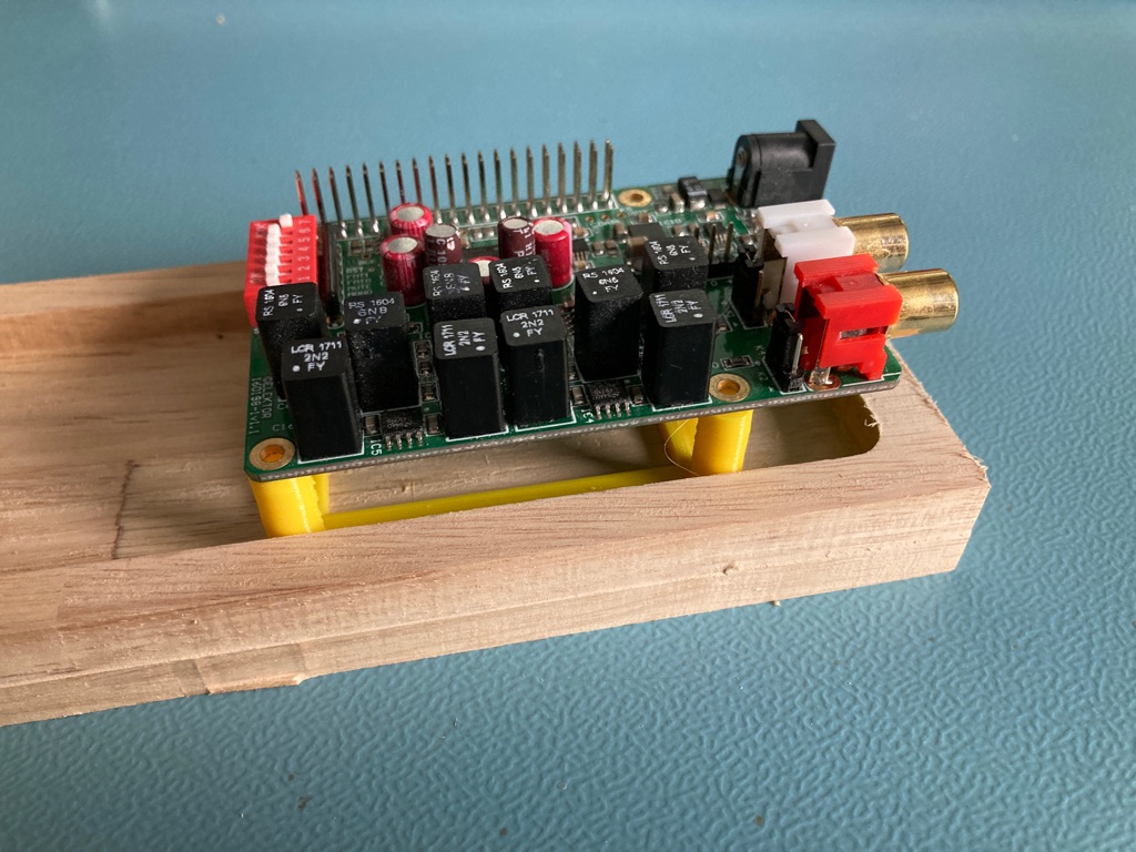
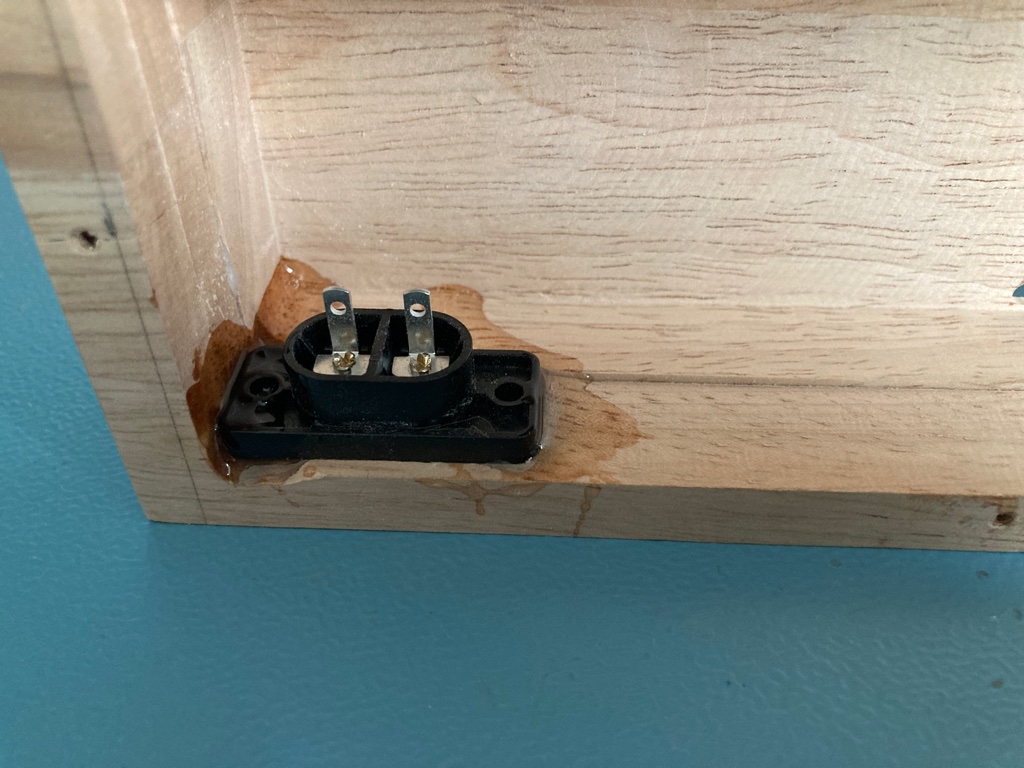
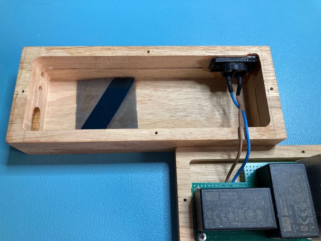
For the openings for the power plug and audio connectors I had to switch back to the good old elbow grease method.

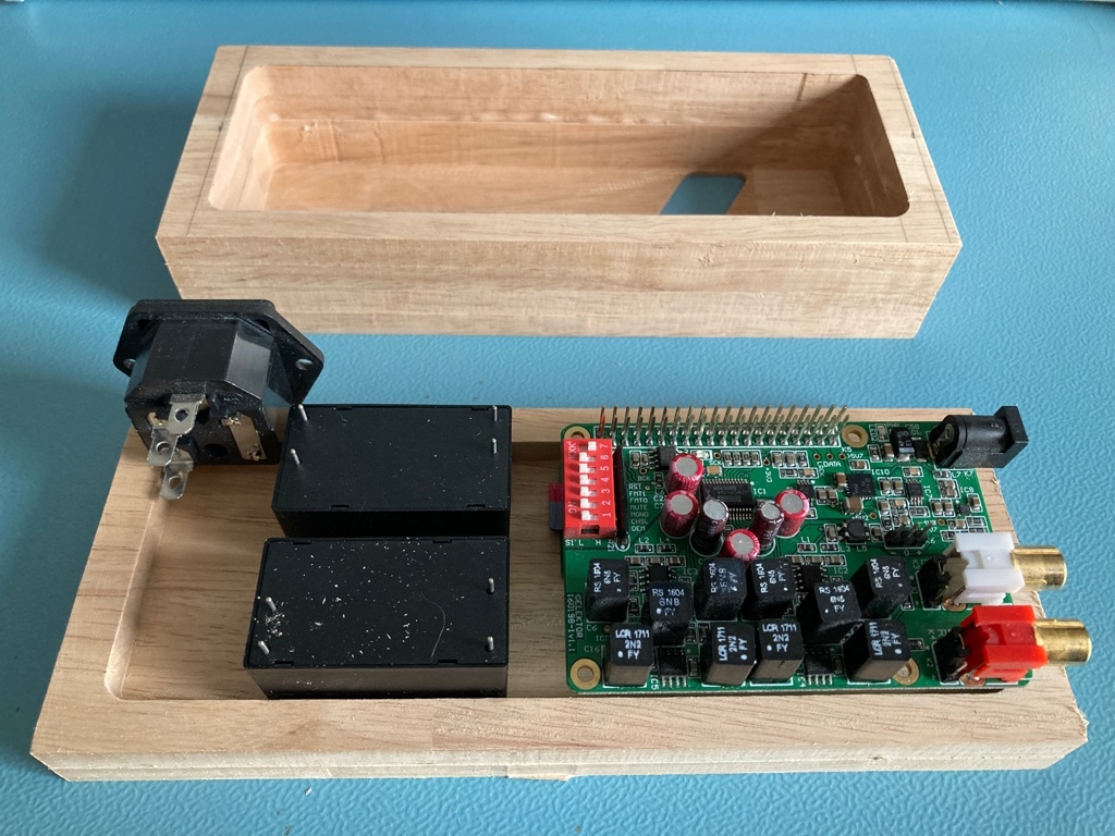
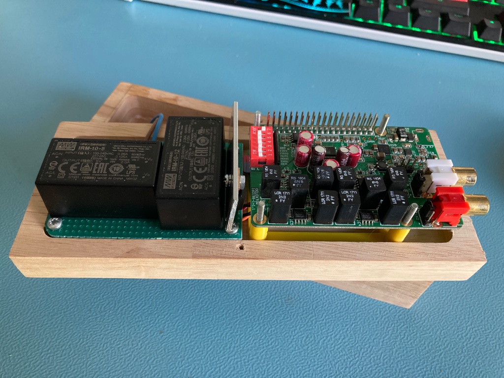
For the power supply, I used 2 small MeanWell IRM-10 10 Watt power supplies. In theory, I could use one power supply and derive both the desired 5V and 8V from it. But I preferred to keep the philosophy of the Elektor DAC and keep both power supplies separated from each other.
Unfortunately, there doesn’t exist an 8V model and I had to use the 12V model. Although
the DAC can regulate 12V down to 5V, the power dissipation of the voltage regulator
would be quite high. Combined with an enclosure without venting holes this might be too
much. I decided to use an 7808 (with a small aluminium strip as a cooling element)
to bring the 12V down to 8V to feed the Elektor DAC to keep everything cool.
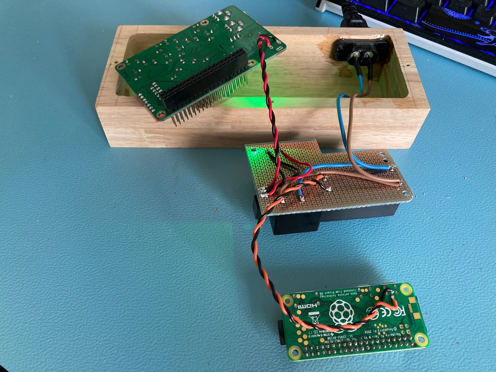
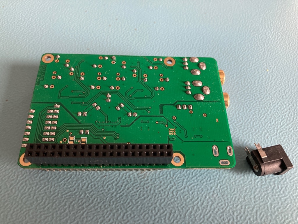
I also had to remove the power socket from the Elektor DAC and directly solder the power wires to it. Luckily removing this socket didn’t take much effort.
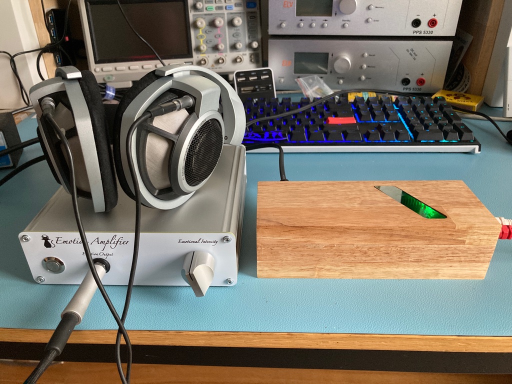
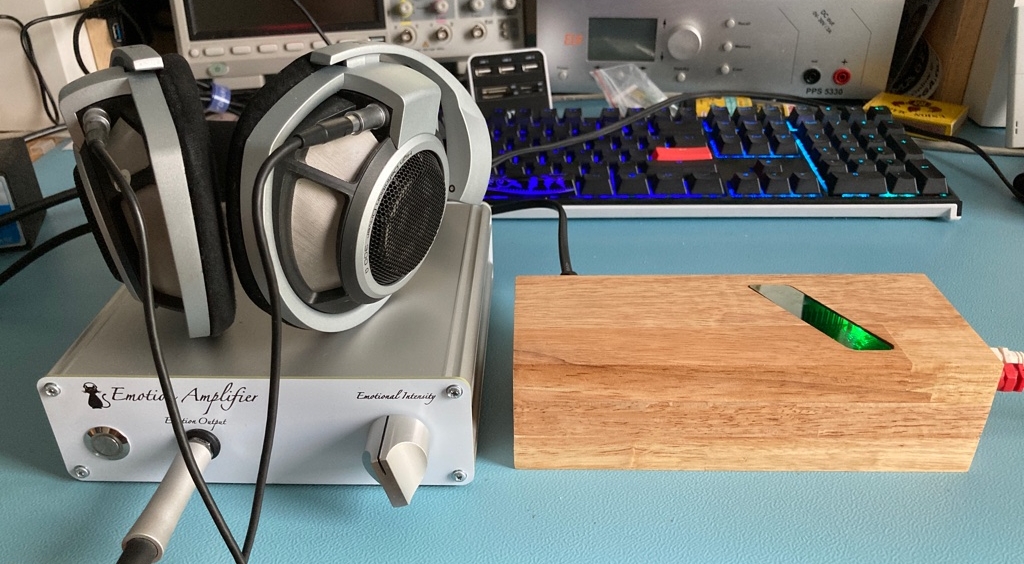
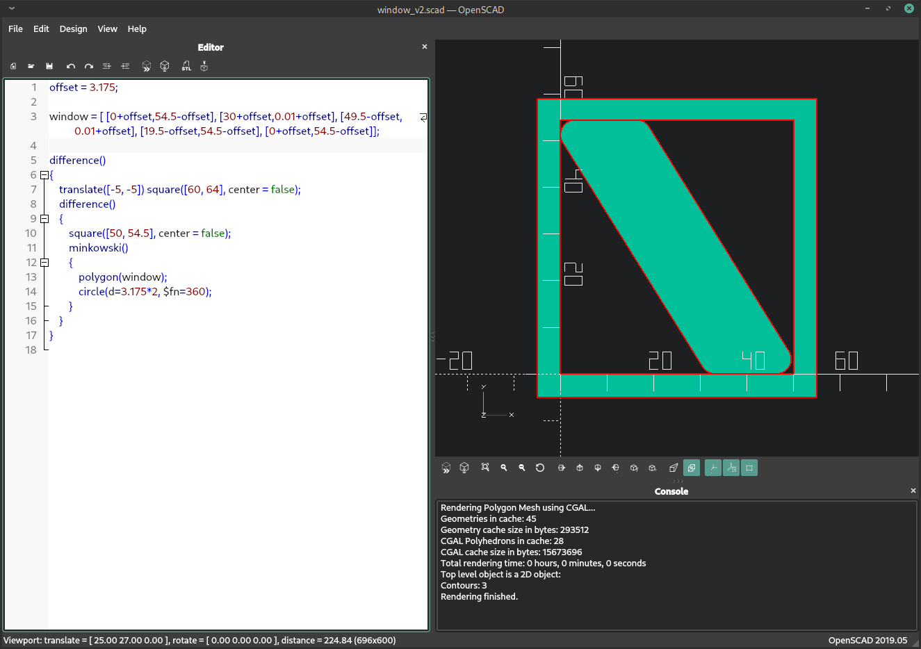
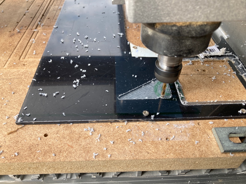
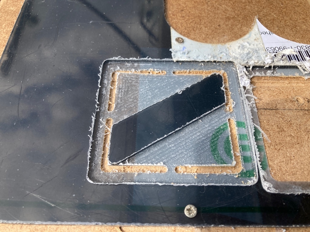
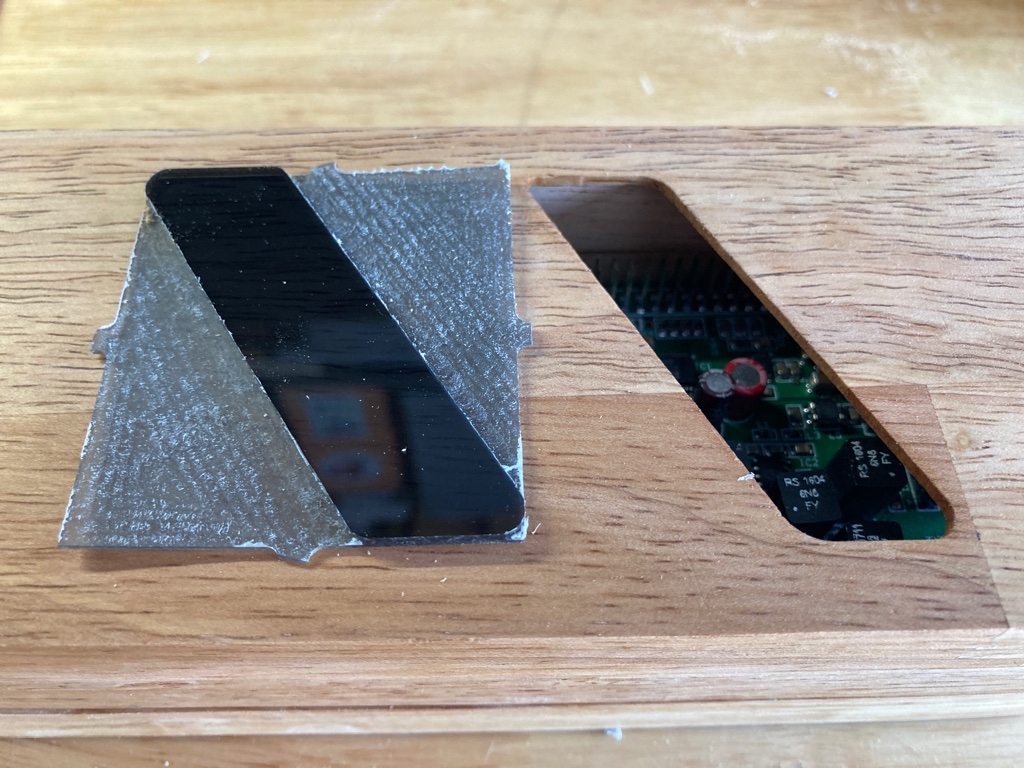
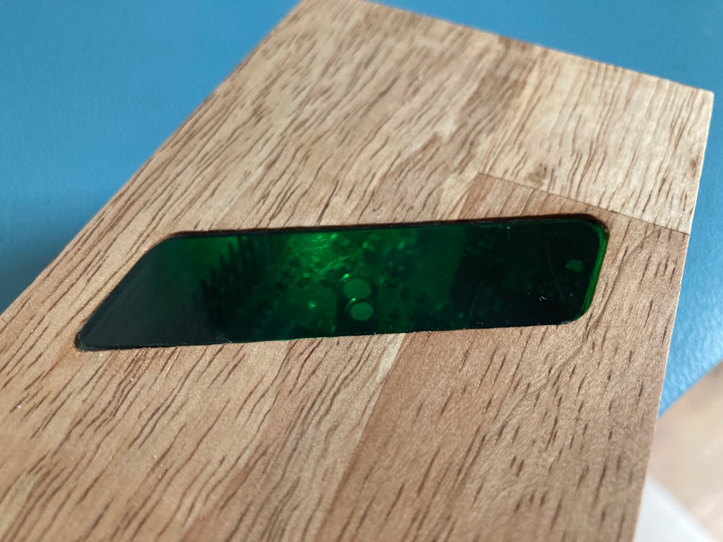
There is a small opening at the top of the box for a window to show off the innards of the box (the green LED is really very bright and easily lights up the complete box). I had some 3 mm thick smoked grey plexiglass laying around from a previous project that I used to fill the window opening with. With my CNC machine I cut away 2 mm of material so that the remaining material fills nicely the window opening. At least that was the theory. In practice some more elbow grease was needed to have a nice fit. This is the openSCAD code I wrote that serves as a template for the plexiglass window.
offset = 3.175;

window = [ [0+offset,54.5-offset], [30+offset,0.01+offset], [49.5-offset,0.01+offset], [19.5-offset,54.5-offset], [0+offset,54.5-offset]];

difference()
{
    translate([-5, -5]) square([60, 64], center = false);
    difference()
    {
        square([50, 54.5], center = false);
        minkowski()
        {
            polygon(window);
            circle(d=3.175*2, $fn=360);
        }
    }
}
The final set up