

What is an EMI/RFI Filter?
I found this definition on the website of Radius Power:
EMI Filters, or electromagnetic interference filters, also called RFI Filters or radio-frequency interference filters, are an electrical device / circuit that mitigate the high frequency Electromagnetic noise present on the power and signal lines. The high frequency noise is generated by a variety of electrical and electronic devices such as motors, electronic controls, power supplies, inverters, clock circuits, microprocessors, appliances, electronic devices etc. This noise is typically in the 9KHz to 10GHz frequency range and it can degrade or prevent the signal transmissions and/or the intended performance of an electrical/electronic equipment. The lower frequency components of the EM noise can impact the power quality as well.
The Industrial EMI Filters provides a low impedance path to the high frequency noise and reduces it by either cancelling its line and neutral components or by grounding it. The effectiveness of an EMI/RFI filter measure as insertion loss (in dB over the frequency range). An EMI Filter is usually most useful for the Electromagnetic noise is 9KHz to 30MHz frequency range which is conducted through the wires. The frequencies beyond 30MHz are typically radiated (travel through the air) requiring shielding and input/output isolation. For radiated frequencies, the filter mounting is more critical than its insertion loss performance.
As we can see from the measurements I made in the take 2.5 blog post, adding an EMI filter results in noticeable cleaner output. So it would be foolish not to use an EMI filter.
Installation
The EMI filter I used (which included a power socket as well) for my tests is unfortunately way too big, demanding that the transformer would be located somewhere else, which means redesigning the PCB again which was something I didn’t want.
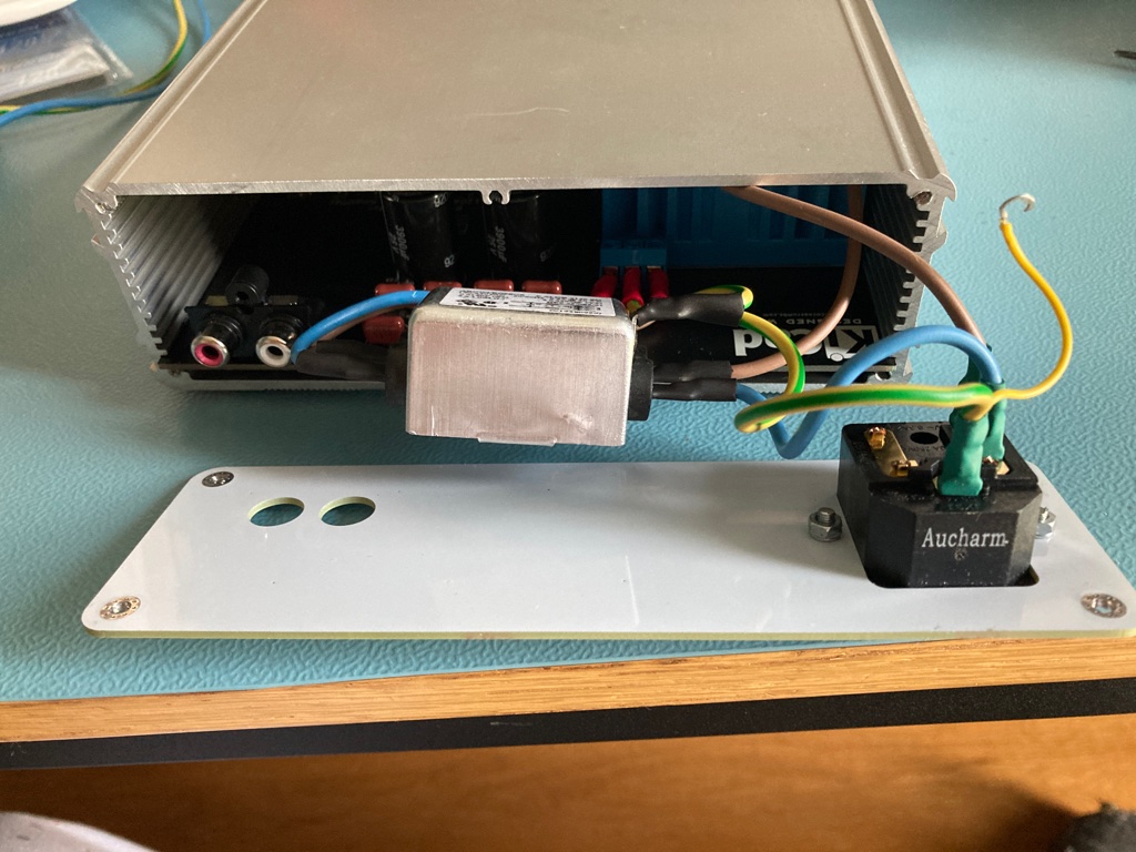
Luckily I found a smaller EMI filter (without a power socket) in my local hardware store:
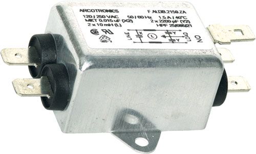
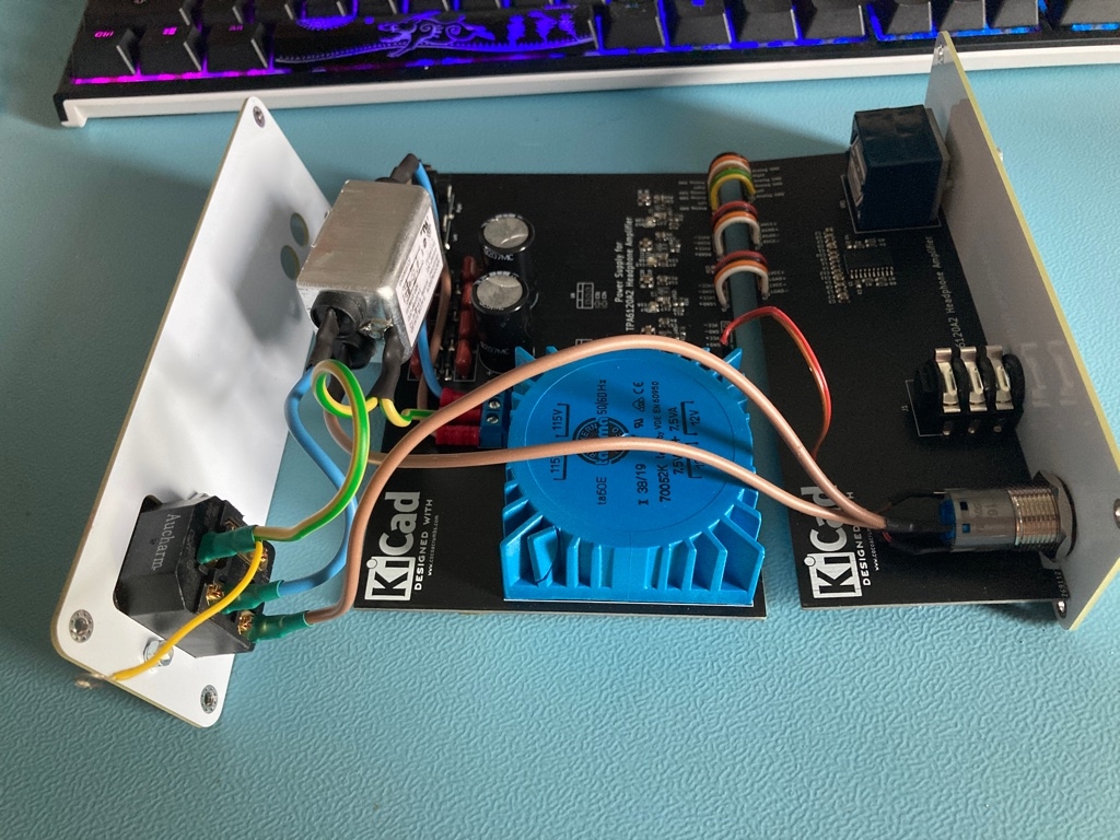
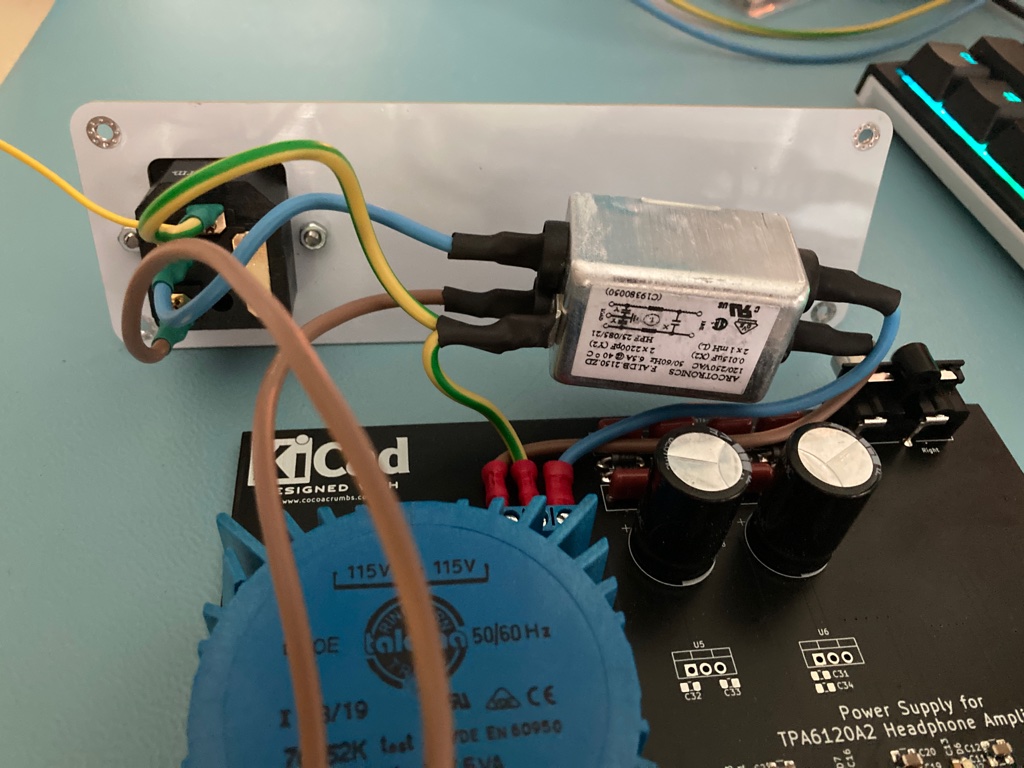
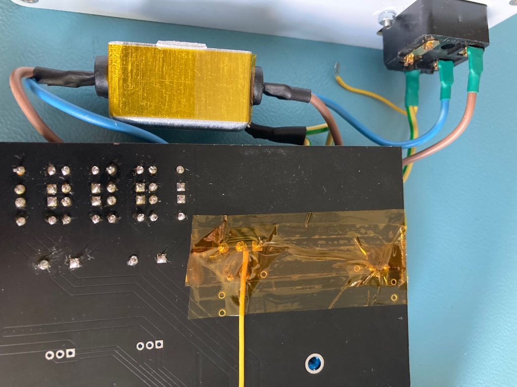
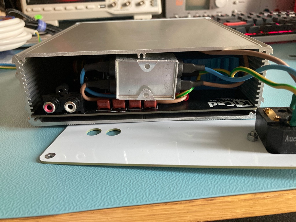
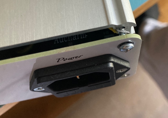
Here are a series of photo’s illustrating how I convinced the EMI filter to fit inside the closure. Notice the use of Kapton tape as well which I used to cover the solder joints which carry lethal voltages to be 100% sure they wouldn’t make contact with the metal enclosure (which is earthed as well of course).
Sobering final thoughts
As already mentioned several times, this headphone amplifier sounds extremely good (my Sennheiser HD800 definitely sings now) and I prefer it over the other headphone amplifiers I have, including the Crack, Oppo HA-1 and the M3.
It’s amazing what this little, $3 chip can do if you take some care in the PCB design, give it clean power and select good components. However, this also feels as if headphone amplification is a solved problem. Better than this will be hard to get and will probably only show as even better distortion figures (which are already so vanishingly low that we can’t hear the distortion anymore). But there will always be a market for headphone amplifiers (sometimes with eye watering prices) that by luck (or by design) match with a particular headphone, maybe introduce some ear pleasing harmonic distortion and make its owner very happy.


