

Intro
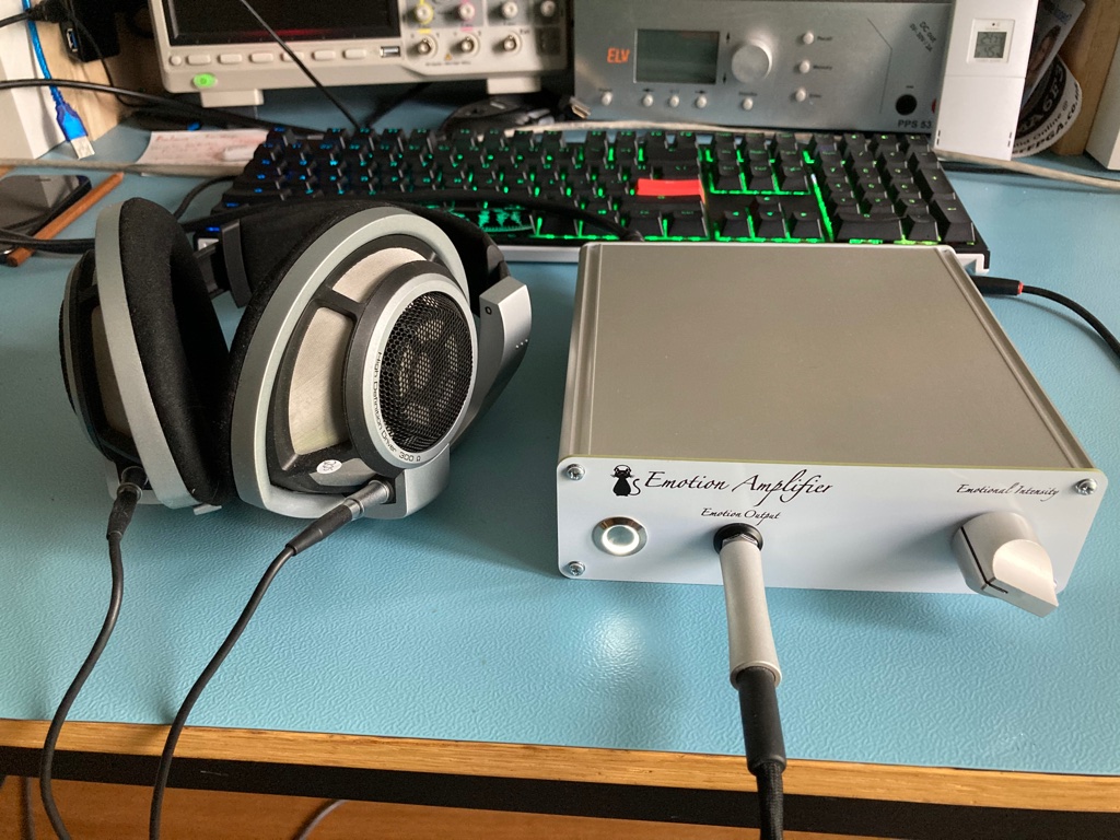
After the successful prototype around the TPA6120A2 headphone amplifier I wanted to build something that could easily be used day by day on your desktop or next to your listening seat. I.e. having a nice enclosure, preferably with a build in power supply (I hate those wall-warts). Hence a take 2 of the design where I also took the opportunity to try out some new things.
Overview
This time the design started with the enclosure I choose for the headphone amplifier. Since this dictates the size and layout of the PCB’s used. In the end I settled on the REDS160 enclosure from Evatron. It’s made from extruded aluminium which is designed to accept 160mm wide PCB’s. That’s big enough to contain both the headphone amplifier, power supply (including the transformer) and necessary connectors.
In the end I decided to use 2 PCB’s (one each for the headphone amplifier and the power supply) instead of one big 160 by 160 mm PCB.
Schematic
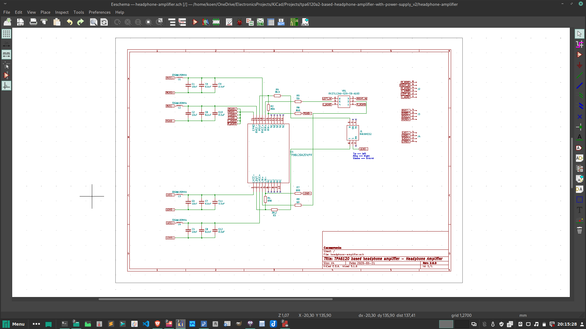
No surprises here. The schematics is the same as from the prototype but is now split over 2 PCB’s.
For the power supply, there is now also room to use the cheap 78xx/79xx voltage regulators in case one doesn’t want to use the much more expensive (and much more difficult to solder as well) LT3045/3094 voltage regulators.

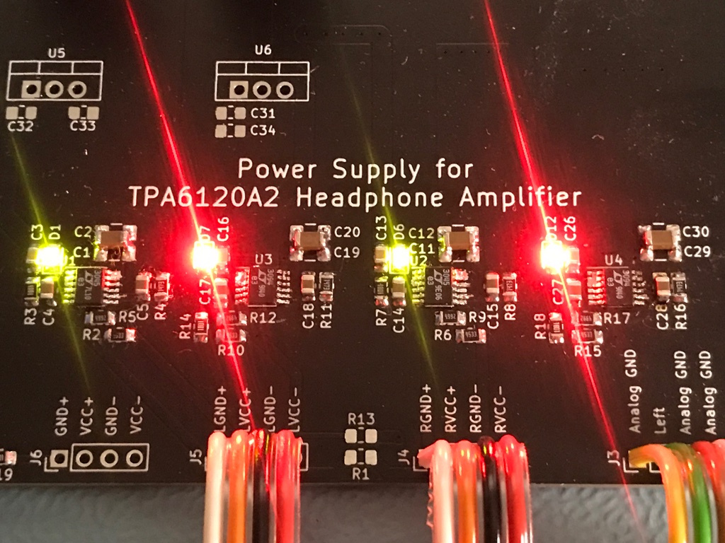
PCB layout
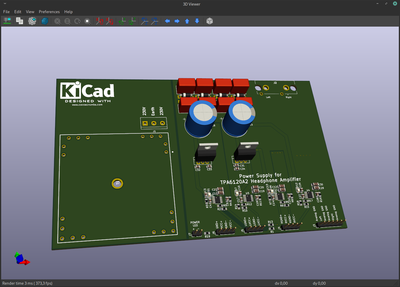
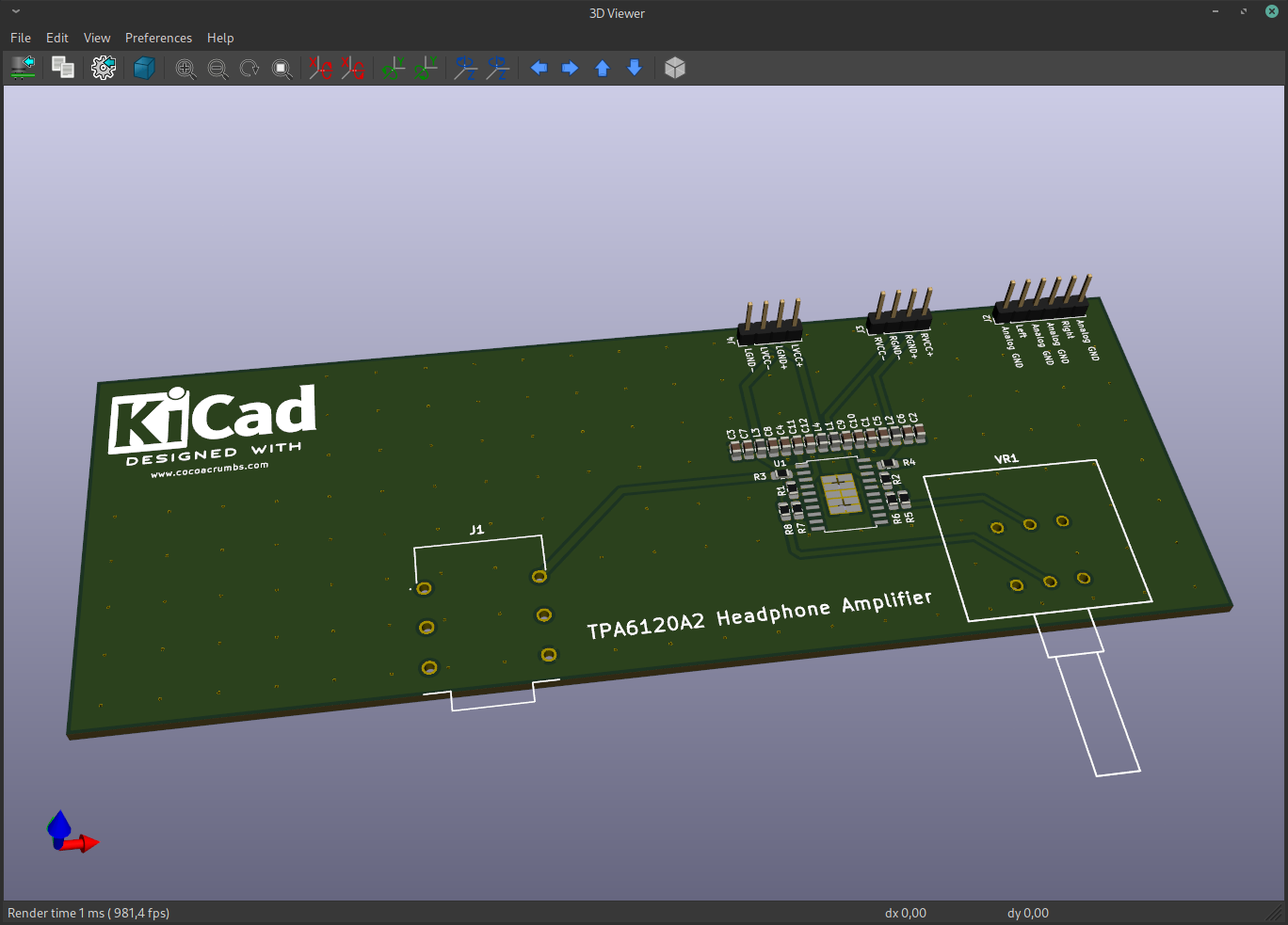
No surprises here neither. I did spend a bit more effort this time to closely follow the PCB layout guides from Analog Devices for the LT3045/3094 voltage regulators to wring out the last drop of performance out of them (having plenty of room helps a lot to avoid making compromises).
For the transformer I choose the 2 x 12 Volt / 15 VA 70052K from Talema. That seems to be a popular choice in the audio world but I was surprised how much mechanical noise (50 Hz) hum it makes. In a silent room it can easily be heard. I hope I got an outlier and that this is not the usual behaviour.

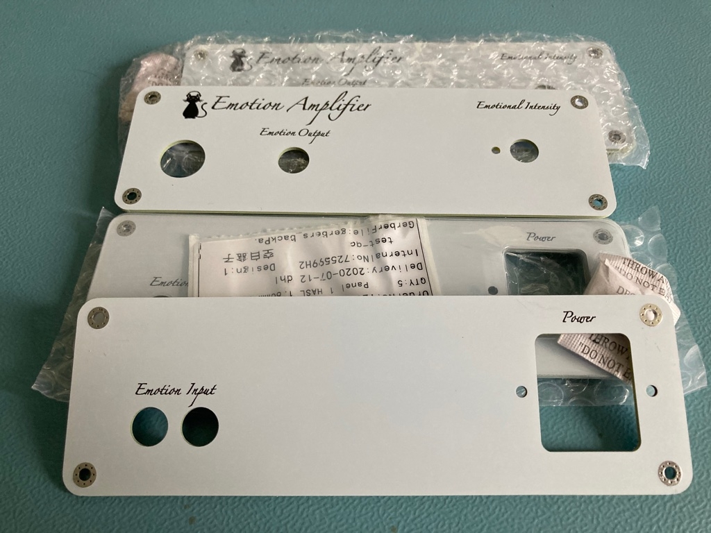
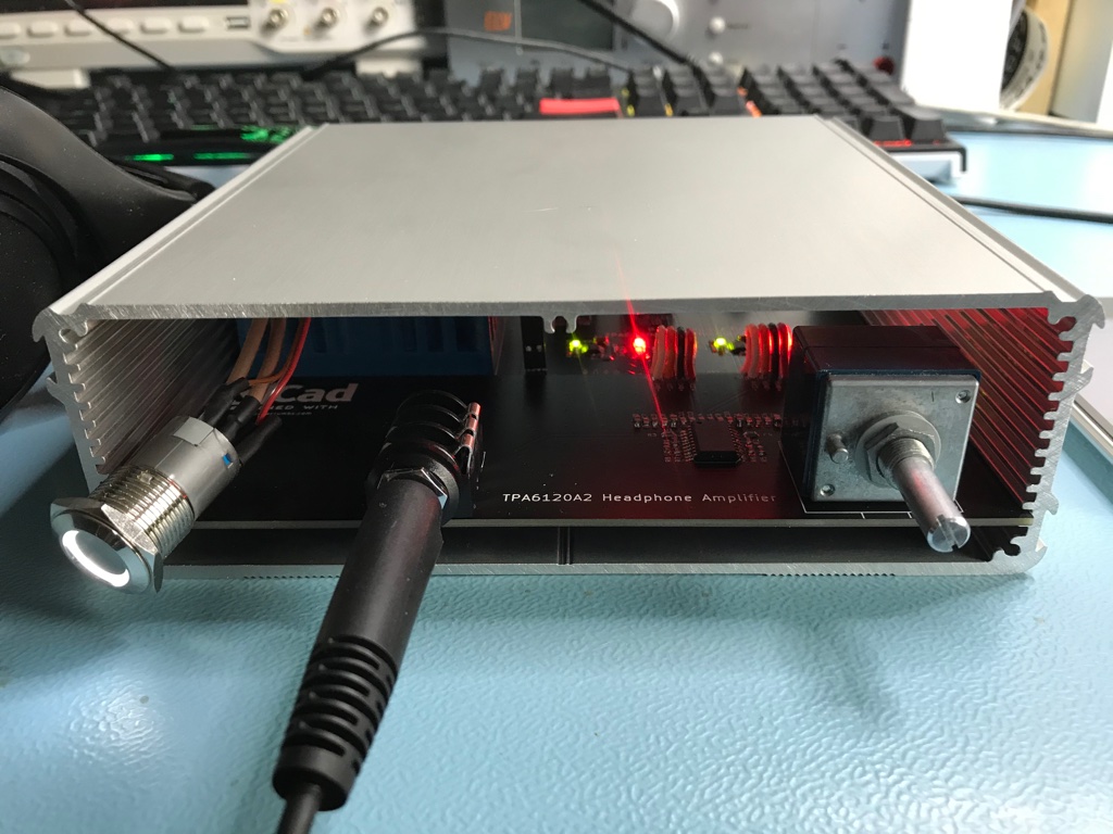
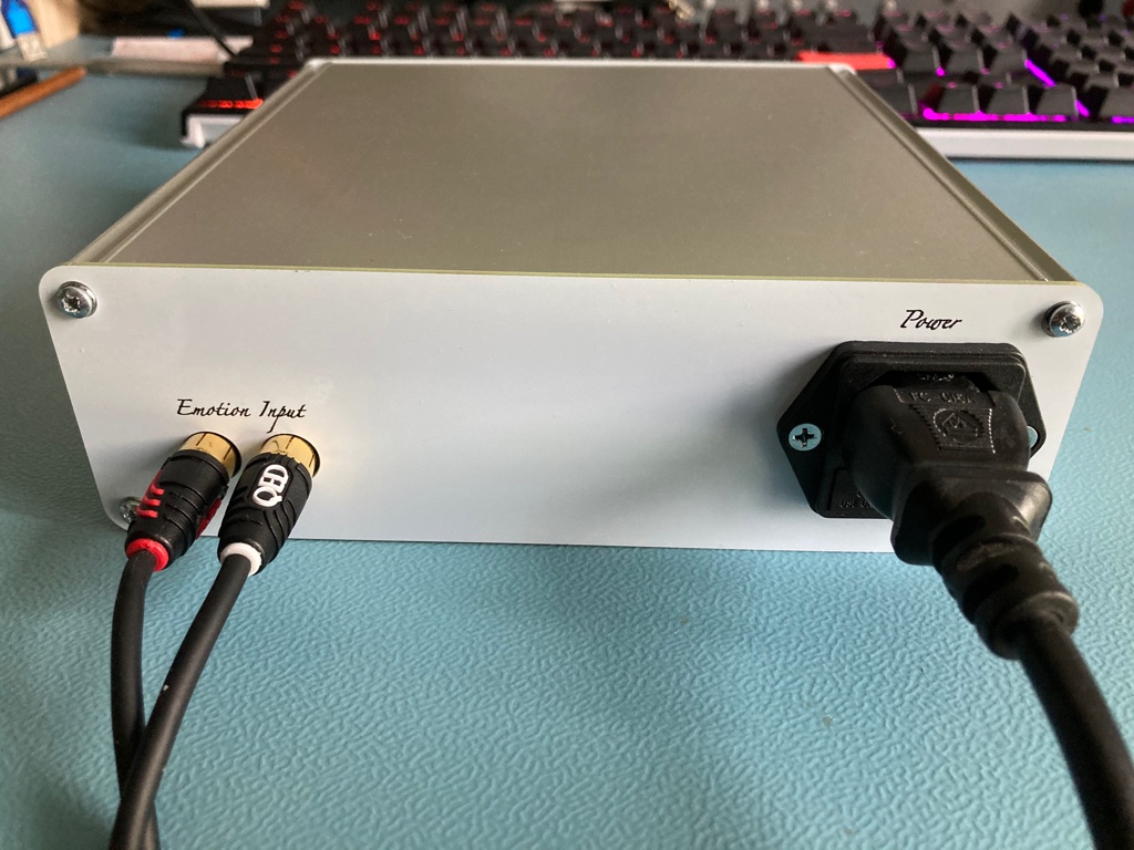
Front/back panel
Of course it would be nice if the amplifier looks good as well instead of the typical prototype look. This means making some nice looking front and back panels. At first I thought to use my CNC machine for it but then I stumbled on a blog post that showed that designing a PCB with a good looking silkscreen can do the same with much less effort.
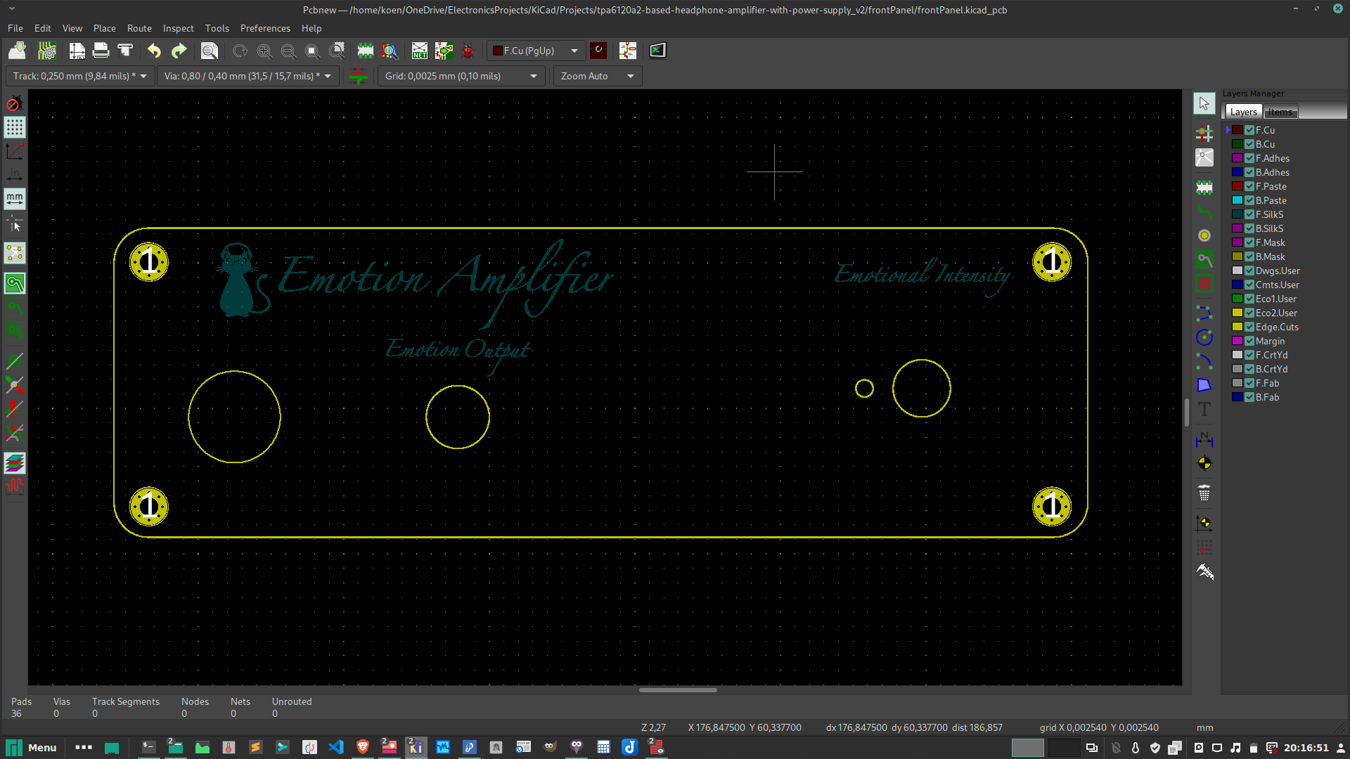
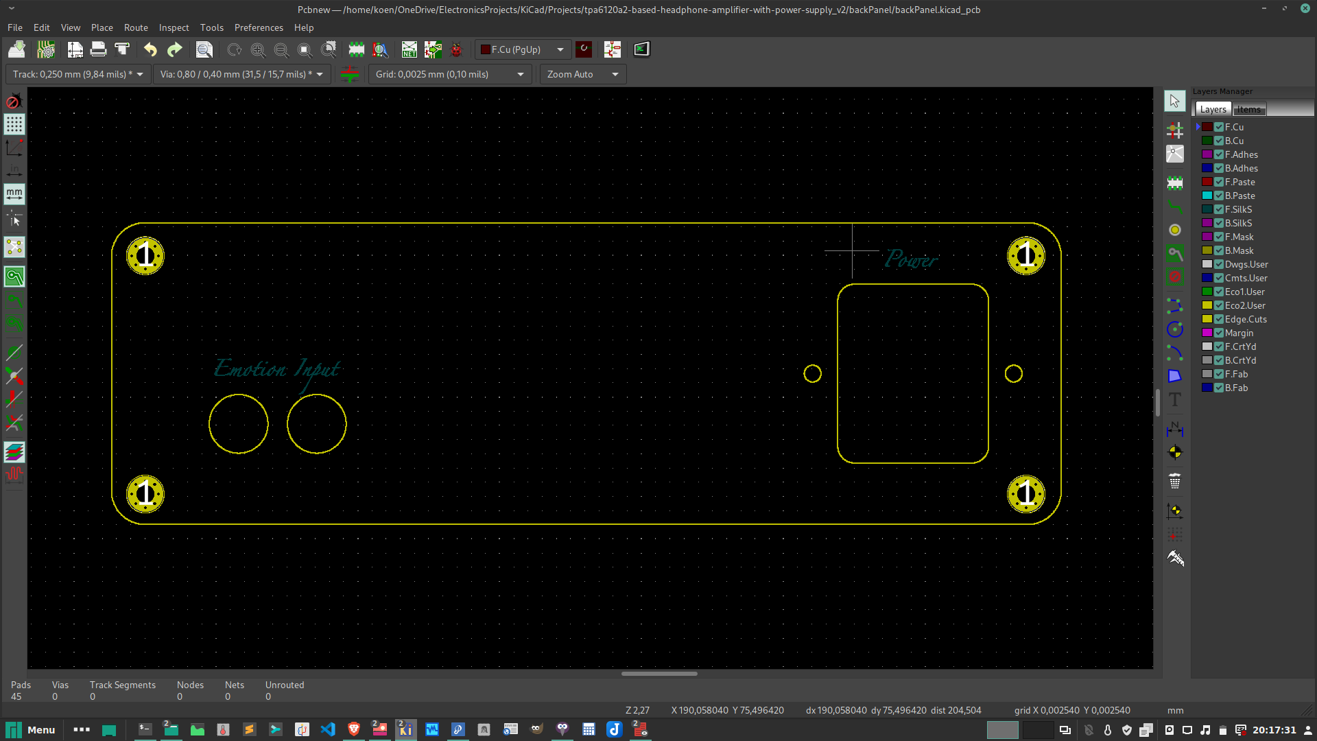
So, I set of designing the front and back panel edges and holes in openScad and imported that in KiCAD.
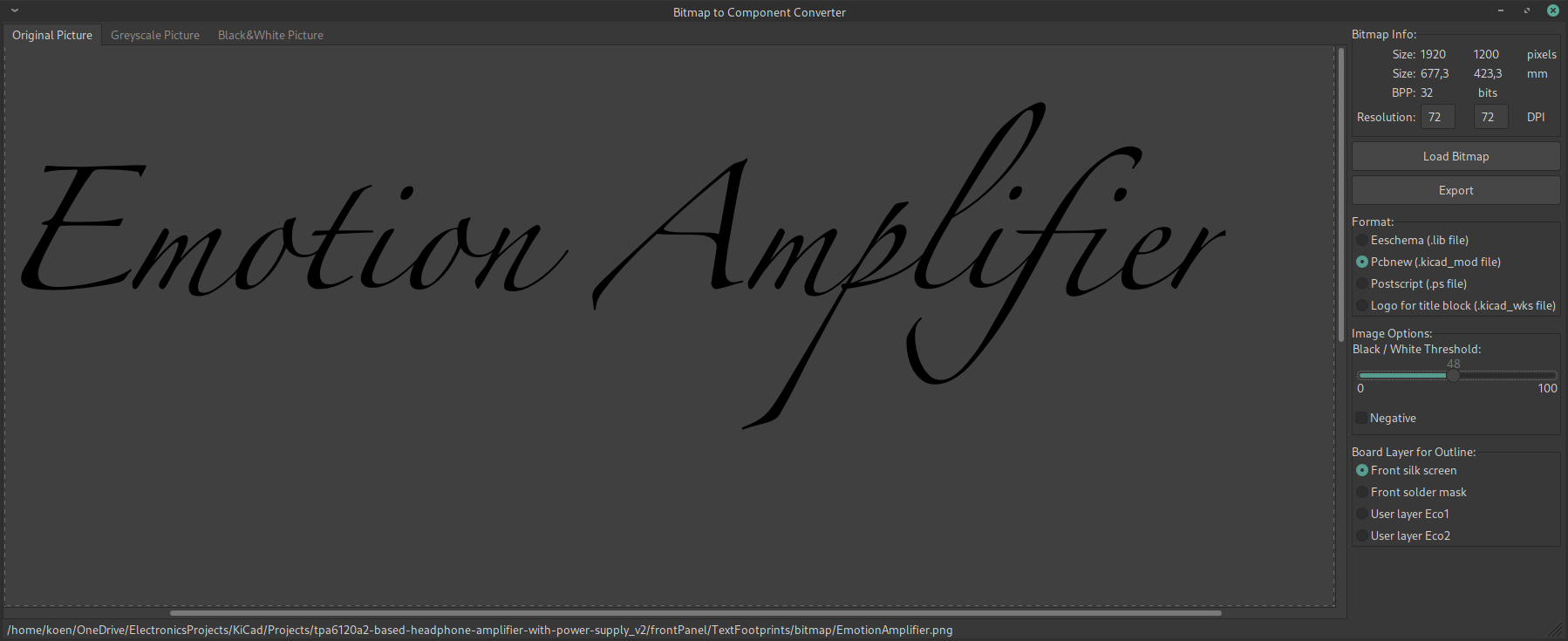
A bit more difficult is adding text in a nice looking font and a cute logo. For this, I created some bitmaps and used the “KiCAD Bitmap to component converter” which converts these bitmaps to footprints. It’s a bit tedious since there is no easy way to scale footprints in KiCAD. To get the correct size I played with various DPI (Dots Per Inch) settings in the “KiCAD Bitmap to component converter” tool until I got the footprint sizes I wanted.
Ordering the back/front panel
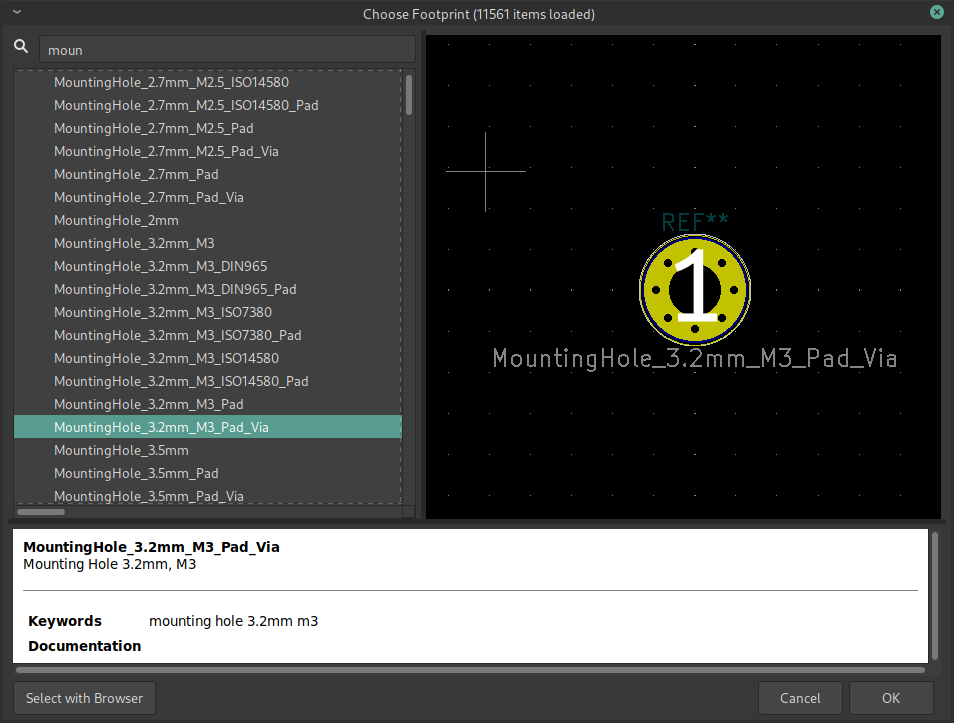
As it turned out, this was a bit less evident than thought and I got some emails from JLCPCB where I ordered the front/back panels that they could not manufacture the PCB because some layers were missing. This was true because there were of course no copper layers for these designs and no drill file neither. I solved this by using mounting holes that act as via’s at the same time for the 4 screws in the corners that hold the panels to the enclosure. That provided a bit of copper on both sides and created a drill file as well since this footprint adds some small via’s as well. With this, I got non empty gerber files which made JLCPCB happy.
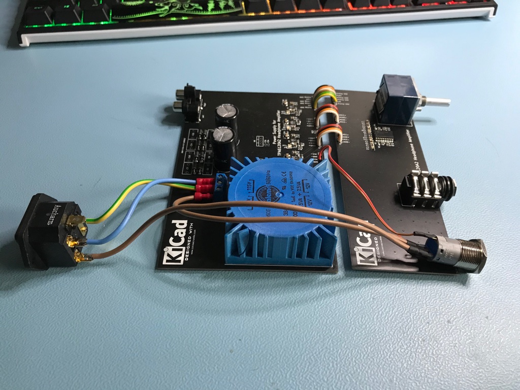
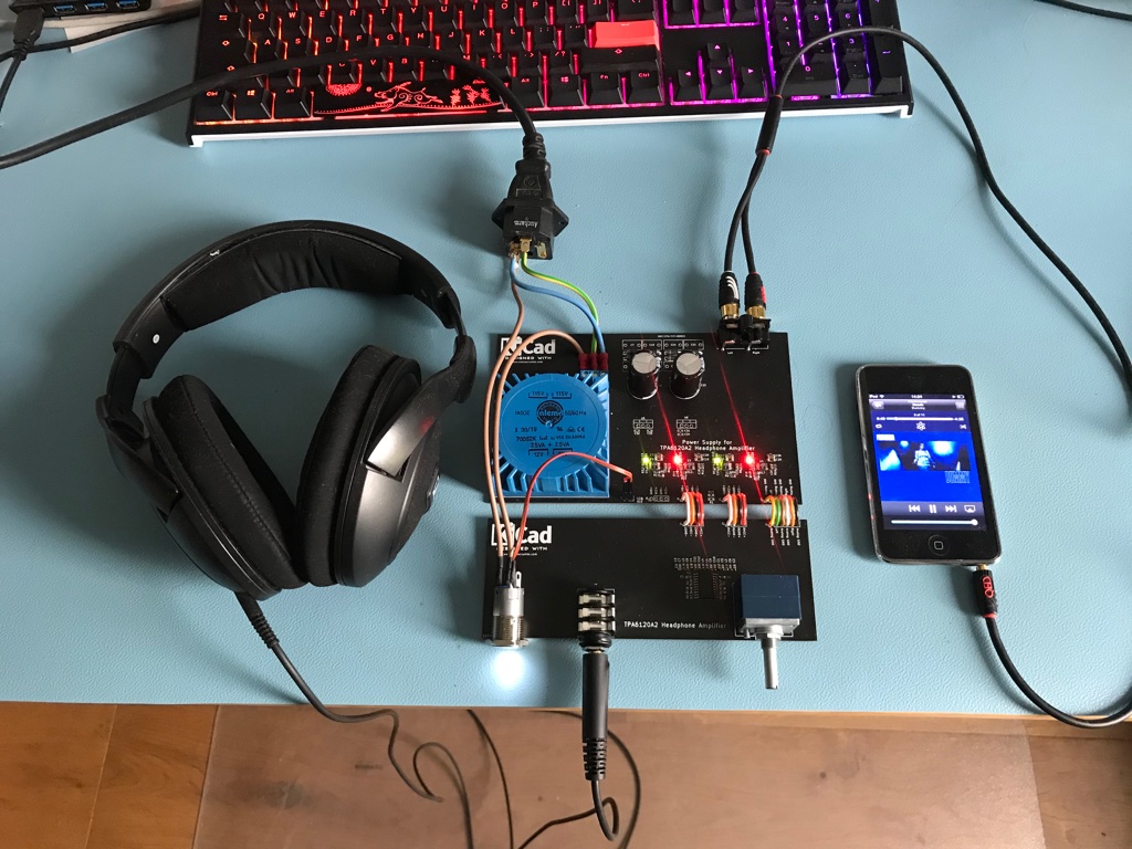
Assembling
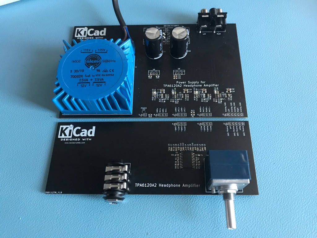
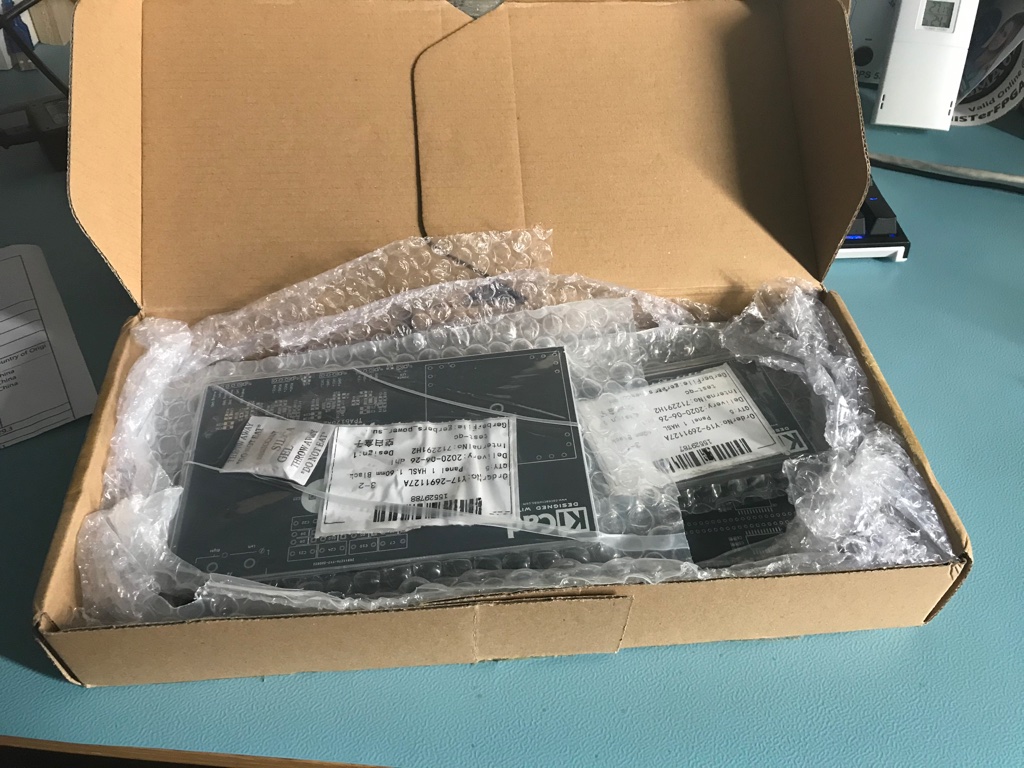
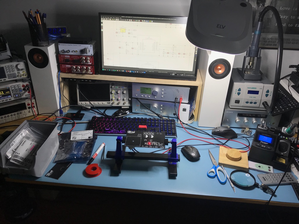
Some pictures I made during assembling the headphone amplifier.
Room for improvement…
The measurements in this section are not correct. Please read the follow-up post I made explaining what went wrong and the real results.
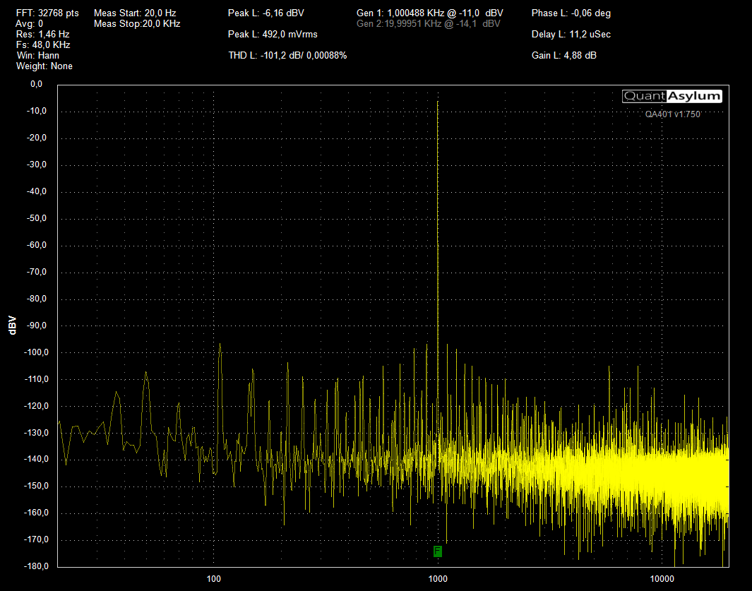
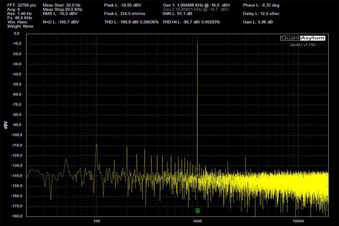
Since I was a bit suspicious that the reason why the prototype sounded so good (even on my Sennheiser HD800 headphones) might be due to lots of harmonic distortion (of the kind human ears seem to like) I decided to buy the QA401 Audio Analyser from QuantAsylum. And I’m happy to report that the Total Harmonic Distortion in both cases is bigger than 100 dB (or less than 0.001%). However, it’s also clear that there is definitely room for improvement.
Despite the fact that the power supply is now on its own PCB, a lot further away from the TPA6120A2, we can see plenty of spikes at multiples of 100 Hz (generated by the full bridge rectifier). And they’re a lot more noticeable in the take 2 version. Not sure yet, but this might be a problem of the different grounding strategy I tried out on the power supply board which also does carry the analog input connectors and brings the analog signal to the headphone amplifier PCB. That will be the first thing I will look into:
So, there will be a take 3 on this amplifier to clean this up somewhere in the future. But that will not hold me back to enjoy its performance and it has no problem amplifying the emotions of music.


