

Since I was so impressed with the performance of the TPA6120A2 I decided to build a more finished product which you can find in a later blog post TPA6120A2 based headphone amplifier - Take 2
Intro
A couple of months ago I got intrigued by a glowing review of the Sony DMP Z1 Digital Music Player. Their conclusion was that the headphone amplifier section seemed to be worthy of the $8.500 asking price. The article also mentioned that the headphone amplifier was based around the Texas Instruments TPA6120A2 chip. Looking at a few key specs, it certainly seems to be very good:
- SNR of 128dB A-Weighted.
- THD of 112.5dB
- Current-Feedback Architecture
- Output Voltage Noise of 0.9µVrms at
- Gain = 1V/V (16Ω Load)
- Power Supply Range: ±5V to ±15V
- 1300V/µs Slew Rate
- Can be configured for Single Ended or Differential Inputs
- Independent Power Supplies for Low Crosstalk
Such stellar specs can’t be cheap, right? Heading over to my usual supplier (Mouser) learned me that this chip cost less than 3 Euro’s, in single units… (2.73 Euro at the time of writing). Now, I got really interested.
What I found interesting as well, this seems to be a current amplifier instead of the usual voltage amplifier and is the first time I see such an amplifier in the wild. For those who want to dive deeper in that topic, a book exist, which might have triggered Texas Instruments to go that way, who knows, Current-Driving of Loudspeakers - Eliminating Major Distortion and Interference Effects the Physically Correct Operation Method by Esa Meriläinen. A good review of that book can be found at AudioXpress. A paper on this topic, by Nelson Pass, is interesting as well: Current Source Amplifiers and Sensitive / Full-Range Drivers
Looking around on the Interweb, I found several designs that used this chip but all of them seem to skimp on the power supply quality by using the traditional 78xx/79xx or LM317/337 regulators.
The irony of the current digital chips (as used in smartphones, PC’s) is that they require super regulated power supplies with the least amount of ripple possible. As such, these regulators are very well suited to feed the TPA6120A2 with clean power as well. In the past I already used the LT3045 from Analog Devices which is a Ultra low Noise, Ultra high PSRR Linear Regulator with these specs:
- Ultra low RMS Noise: 0.8µVRMS (10Hz to 100kHz)
- Ultra low Spot Noise: 2nV/√Hz at 10kHz
- Ultra high PSRR: 76dB at 1MHz
- Output Current: 500mA
- Wide Input Voltage Range: 1.8V to 20V
- Single Capacitor Improves Noise and PSRR
- 100µA SET Pin Current: ±1% Initial Accuracy
- Single Resistor Programs Output Voltage
- High Bandwidth: 1MHz
- Programmable Current Limit
- Low Drop out Voltage: 260mV
- Output Voltage Range: 0V to 15V
- Programmable Power Good
- Fast Start-Up Capability
- Precision Enable/UVLO
- Parallelable for Lower Noise and Higher Current
- Internal Current Limit with Foldback
- Minimum Output Capacitor: 10µF Ceramic
- Reverse-Battery and Reverse-Current Protection
- 12-Lead MSOP and 10-Lead 3mm × 3mm DFN Packages
And quite recently, Analog Devices also introduced its counterpart for negative voltages, the LT3094 with identical specs. So, this is a nice opportunity to use both and see how well they work in an analog circuit.
Schematic
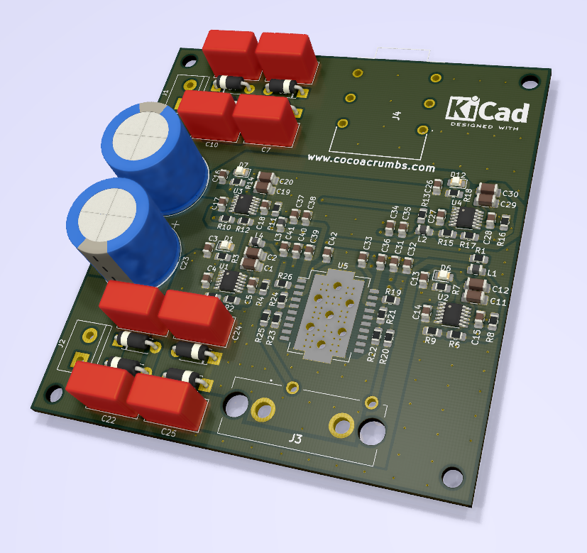
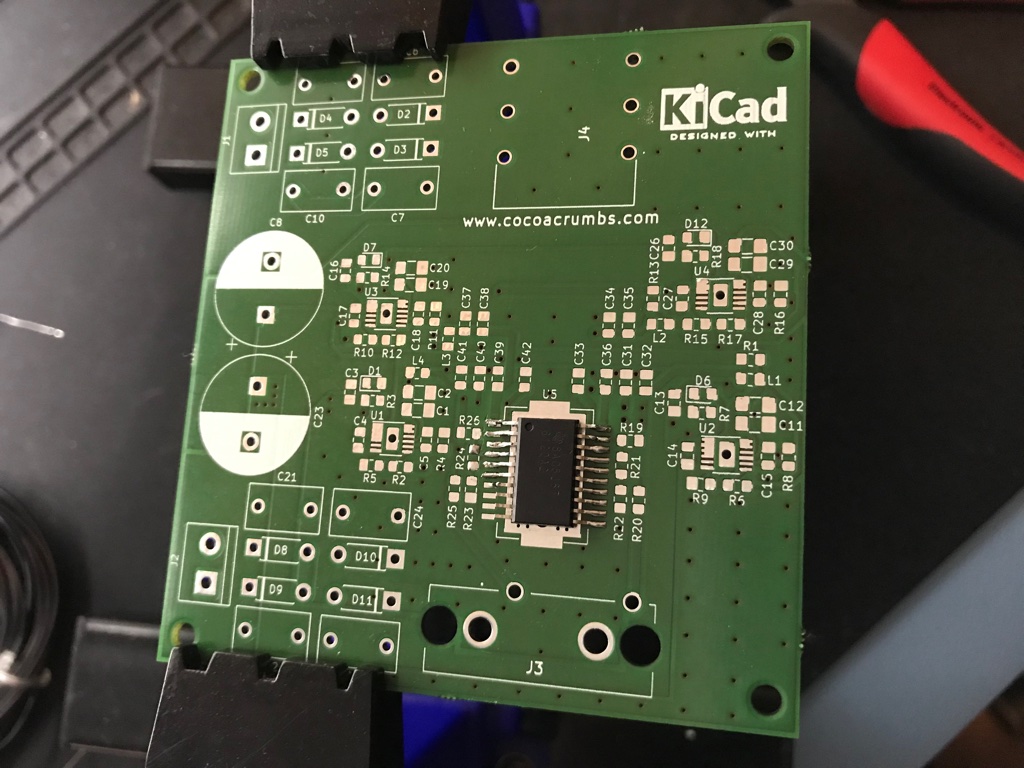
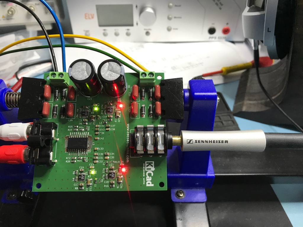
I used KiCad to draw the schematics and laying out the PCB. For convenience, I used 2 sheets for both the power supply and the headphone amplifier itself.
Power Supply
First, I’d like to point to an interesting Application Note from Texas Instruments: AN-1849 An Audio Amplifier Power Supply Design which I feel gives quite a lot of valuable tips and design information for power supplies in audio applications.
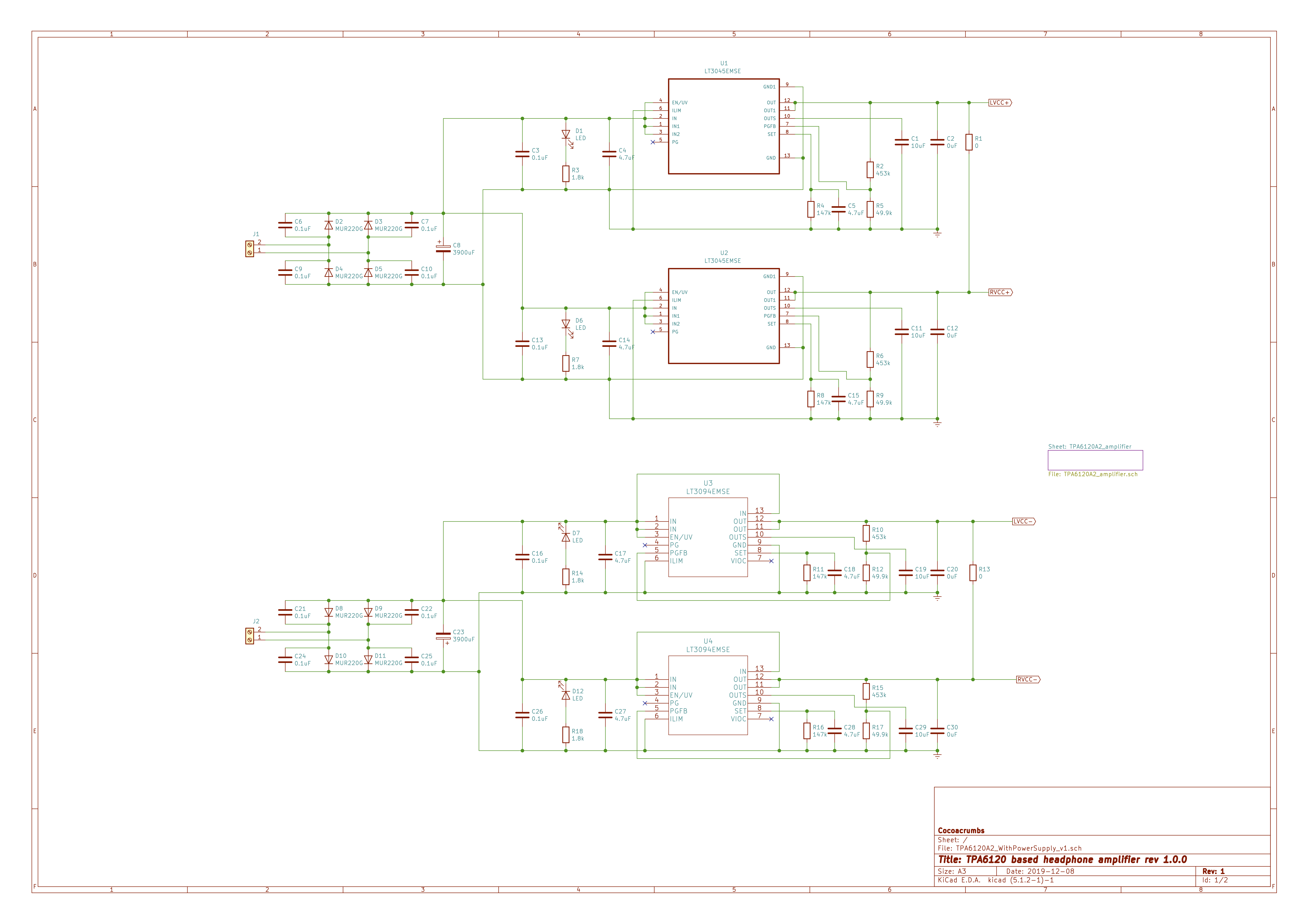
I went a bit over the top for this power supply. Not only opting for the LT3045/3094 combo but also using 2 pairs of them to power both the left and the right channel of the TPA6120A2 (this chip does allow to power left and right separately which can improve crosstalk performance further).
For the full bridge rectifier, I opted for ultra fast recovery MUR220G diodes and snubber capacitors across them to reduce high frequency noise. With 3.900 µF the reservoir capacitors might be a bit oversized but in this application bigger is better.
The PCB layout has been made so that you can use a single pair of LT3045/LT3094 to power the TPA6120A2 (to save costs). In that case, use 0 Ohm resistors (or bridge) for R1 and R13 (otherwise leave these open).
All components use 0805 packages (which can still easily be hand soldered). With the exception of C1, C11, C19 and C29 which use 1206 packages and this because these capacitors require a 4 wire connection to the LT3045 or LT3094. From the LT3045 data sheet:
The LT3045’s OUTS pin provides a Kelvin sense connection to the output. The SET pin resistor’s GND side provides a Kelvin sense connection to the load’s GND side.
In KiCad, I simulate the Kelvin connection with a dummy (0 µF) capacitor parallel over the actual capacitor. That’s why you see C1 & C2, C11 & C12, C19 & C20 and C29 & C30 pairs in the schematic. Using a 1206 package made this a bit easier to accomplish.
I used a toroidal transformer of 2 x 12 Volt AC (30 VA which is bit overkill but I couldn’t find anything smaller). This resulted in around 17 Volt DC before regulation. Well below the 20 Volt limit of the regulators and still comfortable above the 14.7 Volt they’re set to. R4, R8, R11 and R16 determine the output voltage of the regulators. I choose 147 kOhms for them, resulting in 14.7 Volt. Just below the maximum input voltage of the TPA6120A2. I also used 0.1% precision resistors for those.
Probably not everyone is interested in using the cleanest power supply or is willing to go through the expense of the power regulators I choose (they cost 6 Euro’s each after all). In that case, you could keep the full bridge rectifier circuit (maybe using cheaper diodes like the 1N4001), drop the snubber capacitors but keep a large reservoir capacitor and use the ubiquitous 7815 and 7915 instead.
Headphone Amplifier
The headphone amplifier schematic is based on the information I found in the TPA6120A2 data sheet and the user guides of the TPA6120A2 Evaluation module from Texas Instruments.

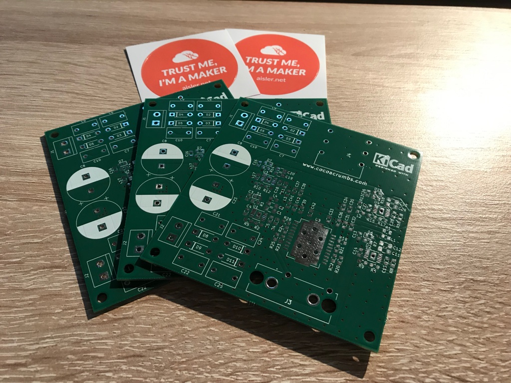
Ordering PCB’s… from Aisler
I recently discovered a non Chinese PCB manufacturer (Aisler) with end prices that are starting to get competitive with the Chinese PCB manufacturers (if you also include the shipping costs into the calculation) . While it’s true that from the Chinese get you 5 or 10 PCB’s for only 2 Euro’s, the shipping costs are typically around 25 Euro. The minimum order at Aisler is 3 PCB’s but shipping cost is free. For the PCB size of this project, they charged 10 Euro per PCB totalling 30 Euro, which is only slightly more in the end and I didn’t have to throw away the surplus of PCB’s I would get from China.
Drawbacks that might be important to you, are that you can’t customise a lot [when you go for the cheapest “Beautiful Boards” option]. E.g. green solder mask only, no gold plating, etc. I’m certainly not an expert but the boards I received certainly look and feel as good as the ones I received from Seeedstudio and JLCPCB in the past.
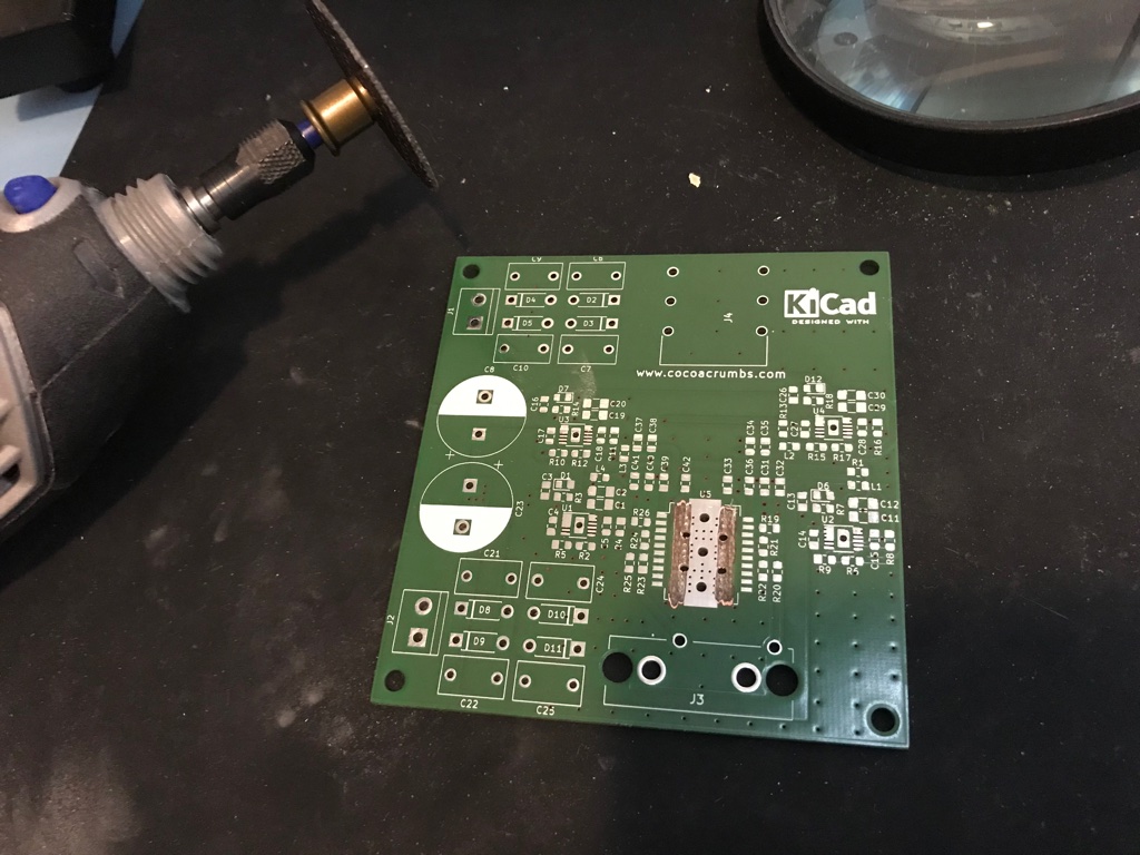
HSOP package mistake
According to the TI data sheet, the TPA6120A2 is using a HSOP20 package (with power pad) which KiCad conveniently has available… Only the HSOP20 package in KiCad is 11.5 mm wide instead of the 7.5 mm of the TPA6120A2 which I didn’t realise until I tried soldering the TPA6120A2 on the PCB…
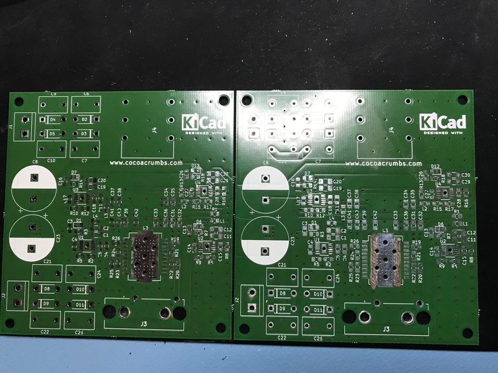
To avoid potential short circuits, I decided to cut away the excess copper pad. So out came the Dremel tool.
A soldering tip to solder IC’s with a power pad
All 5 IC’s have a cooling/power pad on the bottom of their package. And it needs to be soldered to the PCB. For a hobbyist, this would require special tools you typically don’t have available.
I think I’ve found a very simple solution to work around that. In the power pad, I place a via with a quite big diameter (e.g. 2 mm). The procedure is then to first apply a generous amount of flux on the PCB, place the IC and solder the pins. Then turn the PCB, put some more flux again in the big via and then fill it with solder. Hold your soldering iron in the via a couple of seconds to make sure the solder attached itself to the power pad of the IC. So far this little trick has always worked for me.
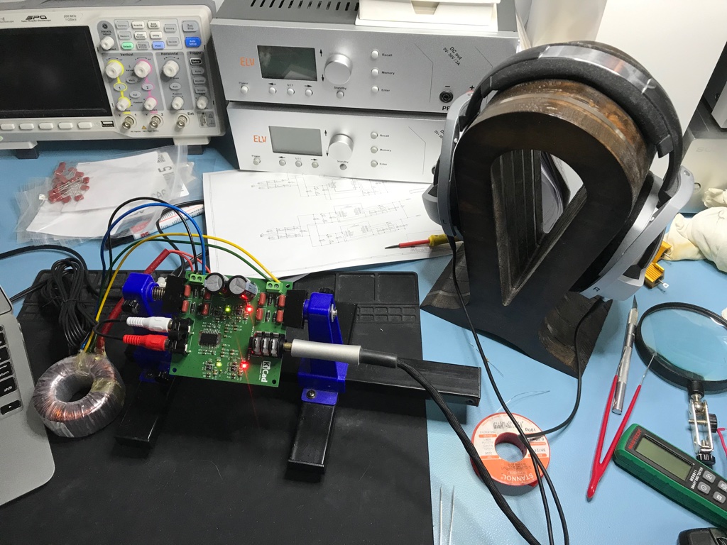
Finished
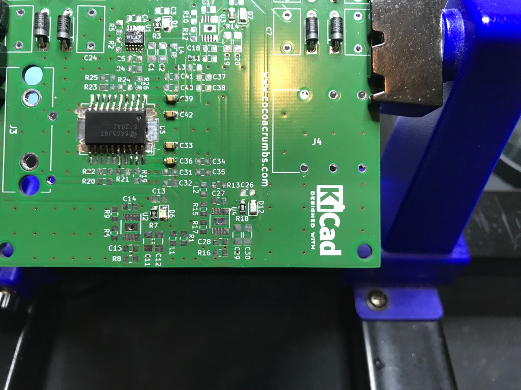
A few photo’s showing the fully assembled board:
Listening
As they say, the proof of the pudding is in the eating. Of course, it’s hard to be objective if you made the board yourself. Also, I’m missing the needed test equipment to do really objective testing. I’m looking into the QA401 Audio Analyser test equipment since Audio Precision equipment is way out my hobby budget (and maybe it would be nice to build my own test equipment in the future). But for now I’ll have to trust my ears (and see the reactions of surprised visitors ;-)
First of all, I was very pleasantly surprised how well it drove the notoriously hard to drive Sennheiser HD800. It has been in use now for quite a few hours and I even took it to work for a week so that I could play it for hours on end without seeing any magic smoke appearing. In fact the board hardly comes warm which is in very big contrast to the Oppo HA1 (which I also have but doesn’t seem to like the HD800) which runs very hot after only a few minutes.
I demonstrated the board to my co-workers as well, showing what a cheap IC is capable of in driving a high-end headphone known for its analytical capabilities without having to pay mega bucks for an audiophile headphone amplifier.
Most surprising is the iron grip it had on the headphones for real bass. Take for example Living Fields from Portico which goes very low (don’t try it on your laptop speakers…). With lesser headphones/amplifiers you just hear a booming bass without any detail. Now, the bass really firms up and smaller details, reverberation, fading out, etc. that used to be lost in the blooming of the booming bass, can clearly be heard/distinguished now. One of my co-worker described it as a dry bass which probably described it best.
Female vocals (typically the ultimate test) didn’t pose any problem at all and it’s pure joy to listen to some of my favourite tracks like Melanie De Biasio - With All My Love and London Grammar - Who Am I
It has also no troubles showing the differences in the quality of your DAC and will certainly benefit from a good DAC implementation.
I want one
You can find the full KiCad project here which includes the Gerber files as well plus a list of all components that were used in the materials folder (just shy of 50 Euro at the moment of writing, excluding VAT and the toroidal transformer). In the doc folder you’ll find some of the mentioned data sheets as well of the chips I used here.


